Bad things happen when programmer finds a soldering iron

No Delays.h

After not touching project for a while, using MPLAB X 3.26 with a newer XC8 compiler (1.37) brought me error: (141) can't open include file "delays.h": No such file or directory. For some reason delays.h got cut from the environment. Fortunately, the only function I’ve used from that header was Delay10KTCYx - one you can directly replace with a _delay macro.

For example

Delay10KTCYx(6);

can be directly substituted for:

_delay(60000);

But that works only up to 19 - values 20 and above will give you error: (1355) in-line delay argument too large.

For those we can always create a more direct substitute:

void Delay10KTCYx(unsigned char count) {
    do {
        _delay(10000);
    } while(--count != 0);
}

Using AN20 on PIC16LF1559

For one pet project, I decided to use Microchip’s PIC16LF1559. as it was close to perfect as far as my needs went in that particular scenario. So I got all parts, soldered it onto the board and it almost worked perfectly.

Single thing that gave me trouble was light detection. It seemed as if ADC converter was giving me nonsense. I check and rechecked my code multiple times as this was the first time I’ve dealt with this chip. It took me a while before I remembered to check errata sheet. And, lo and behold, there was an known issue: “AN20 is not internally connected to the ADC bus when AD2CON0’s CHS bit select the pin.” And guess which pin I decided to use for light sensor?

Initialization of ADC is something that will slightly vary with application but what follows is a reasonable starting point:

ADCOMCONbits.ADFM = 1;      //right-justified
ADCOMCONbits.ADCS = 0b111;  //Frc (clock derived from A/D RC oscillator)
ADCOMCONbits.ADPREF = 0b00; //Vref is Vdd
AD2CON0bits.CHS = 20;       //select AN20
AAD2CHbits.CH20 = 1;        //AN20 is connected to ADC2

This will nicely work around the issue by using AN20 on the secondary channel. Not an ideal situation but it was ok in my case as I had no other plans for secondary channel anyhow.

Reading a value is a bit different than when dealing with a usual, single-channel, setup:

uint16_t getAdcValue(void) {
    AD2CON0bits.ADON = 1; //Turn on ADC

    AD2CON0bits.GO  = 1;
    while (AD2CON0bits.GO_nDONE) { nop(); } //Wait for A/D convert complete

    AD2CON0bits.ADON = 0; //Turn off ADC

    if (AADSTATbits.AD2CONV) {
        return AD2RES1;
    } else {
        return AD2RES0;
    }
}

For my purpose it made sense to turn on/off ADC as needed - for some other scenarios it might be better just to leave it always on. But interesting bit comes when reading a value - ADC saves it interleaved between two registers: AD2RES0 and AD2RES1. Code simply had to make sure to read correct one.

And this, slightly roundabout process, finally got the project working.

Date in a MPLAB Hex File Name

Illustration

Every compilation in MPLAB results in the same file - Source.production.hex (yes, assuming you are not doing debug build). This is perfectly fine if we want to program it immediately. However, what if we need to store files somewhere else and, god forbid, under different name?

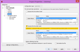
Answer is simple enough. Under Project Properties, Building there is a post build step option. Enable it and get code for copy in. In my case, I wanted to have hex file copied to Binaries directory:

${MKDIR} "Binaries" && ${CP} ${ImagePath} "Binaries/Whatever.${OUTPUT_SUFFIX}"

But simple copy is not necessarily enough. It would be great if we could include date in the file name. And there problems start - there is pretty much no documentation for build commands at all. Only way to figure things out is to see how they are setup by the platform itself in nbproject/Makefile-default.mk and nbproject/Makefile-local-default.mk. To cut a long story short, there is a way to get output from external command. Just wrap any command in completely unexpected $(shell ) pseudo-variable.

In order to get actual date I prefer using code>gdate (comes with MPLAB installation). Using it our line becomes:

${MKDIR} "Binaries" && ${CP} ${ImagePath} "Binaries/Whatever.$(shell gdate +%Y%m%d).${OUTPUT_SUFFIX}"

Finally after build we will have both our usual Source.production.hex and also a copy of it under Whatever.20150128.hex.

How Fast Can You Charge?

Recently I saw SONICable Indiegogo project promising to double the charging speed on computer. It is supposedly an advanced USB cable with a magic switch cutting your charge times in half. But not everything is as it seems.

First onto a topic of “unleashing double the charge power of the regular charge cable”. As you might know, USB standard limits current to any USB device at 500 mA. What is not obvious from this is that even now you can have devices pulling much more than this - all the way until small fuse stops you. Devices obeying the standard pull 500 mA because they are well behaving citizens - not because USB restricts them from more. Just measure current of any USB cup warmer. :)

Some devices, mobile phones in particular, also have a fast charging mode that triggers when they detect a wall charger. Detection method itself used to be different for every manufacturer. Fortunately they got standardized into two camps - Apple and everybody else. Leaving Apple aside, most phones use USB Battery Charging Specification. Deep in technical text there is a Dedicated Charging Port (DCP) detection method consisting of “short D+ to D- through resistance RDCP_DAT”. At end specification we have RDCP_DAT defined as maximum resistance of 200 Ω. In laymans terms - just connect the freaking D+ and D- wire together.

Since standard USB cable has four wires (5V, D-, D+, and GND - let’s forget about ID for now), whole high-tech solution is to connect two wires together. That will make device think it is connected to a wall charger and that it can stop being good 500 mA citizen. It is the phone who will then pull around 1000 mA (rarely more) from computer. Since fuses on USB port are intentionally overdimensioned, computer will generally allow it.

There are thousands of YouTube videos alone showing you how you can do this. All you need is to get an old USB cable and cut it open. Then short data wires (white and green) together and voila - you have a cable giving you 1000 mA magic.

There are devices enabling this on eBay. Quick Google search found me The Practical Meter and USB Meter Pro on Kickstarter using exactly the same “magic” as SONICable. Heck, even my UsbAmps uses exactly the same principle from 2013 onward as a button option. Unofficially, there were people seeing me use small screwdriver to connect D+/D- lines way before that. :)

This functionality is nothing special, nothing secret, nothing patentable, and definitely not magic. Paying for a $25 cable promising you magic when all it does is enabling something you can get either for free or for fraction of a cost is crazy in my opinion. To be completely fair, just based on images, it does look as a nice cable - those with fashion in mind might be able to justify $25 cable. Just don’t buy it for its technology.

And remember - with USB 3.1, its new connector, and a new USB Power Delivery standard all this will become pretty much irrelevant side note in the history of USB.

Detecting Watchdog Reset in XC8

Illustration

Watchdog is probably one of the best PIC microcontroller features. Yes, it would be great if you would write perfect code and program would not get stuck in the first place, but let’s face it: mistakes are going to be made. And really, are you going to write timeout code around every communication routine just so you can detect one in million error?

In 99% of cases, you will just turn on WDT timer in your config bits and count on it to reset microcontroller if something goes wrong. If watchdog times out, program will start from scratch and all is good. For all practical purposes, watchdog-initiated restart is same as normal start. Or is it?

Most PIC microcontrollers clear their ~TO bit in STATUS register as a way to detect watchdog restart. However, if you try to read that from your XC8 compiled C program it will seem that every microcontroller start is normal. It will report any timeout. Cause? Because your compiler is clearing STATUS register before your program starts running.

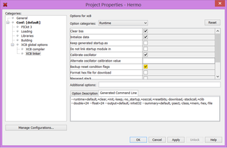
If you are interested in watchdog timeouts, first you need to tell your compiler to preserve startup status for you. This can be done by going into project properties, selecting XC8 linker category and checking Backup reset condition flags item. Now your compiler will give you access to two special variables: __timeout and __powerdown. These variables will be copy of ~TO and ~PD states respectively.

If you read datasheet carefully you will notice that ~TO will be 0 if timeout has occurred. Thus code to check for it would look something as:

void main() {
    ...

    if (^^__timeout == 0^^) { //value 0 means there was a timeout
        //this restart is due to the watchdog timeout - do something here
    }

    ...
}

PS: Procedure described here is specific to XC8 compiler. But same principle applies with most other compilers too.

Jelly Bean PICs

It used to be easier years ago when I started playing with Microchip microcontrollers. You pretty much had only PIC16F84 readily available and that was the PIC you used for anything. Today situation is very different. There is probably a different microcontroller for any purpose you can imagine. However, with time, I more-less standardized on a few of them.

Theme is common. I work mostly with 5 V power supply so anything that can work directly of that is highly desirable. Pretty mandatory is at least one UART port because that is something I use more often than not. I2C and SPI are also high on the list but they sort of go hand-in-hand with aforementioned USART so I rarely specifically search for them.

For most of things I do speed is rarely of concern and any PIC with internal oscillator (keeping component count low) will usually do. Exception is when it comes to USB and CAN bus that are really finicky in that respect.

Quite often my PIC of choice has multiple family members so I can easily go between memory sizes and/or pin counts. Also high on the list are old and proven designs everybody else uses. Why do development around a new and/or unknown PIC if you cannot buy it 90% of the time.

Since most of my soldering is done by hand any PIC that cannot be obtained in SSOP or similar package is automatically out of picture. Having it in DIP format is a small plus but I personally don’t really care about it.

Without a further ado, here is my list of PIC chips I always have available:

PIC16F1826

If I don’t have any special needs I will most probably end up using this little gem. It is rather small in size with only 20 pins SSOP (18-pin DIP), 16 of which can be used for I/O (not all models are this pin-efficient). Alongside 256 bytes of RAM, it also has 256 bytes of data EEPROM available. Basic model has only 2K of programming space but upgrade to 4K model (PIC16F1827) is completely painless.

Features include 10-bit ADC (12 channels), specialized capacitive touch module (12 channels), good UART, and support for both I2C and SPI. It goes up to 32 MHz, all that on internal oscillator module. Only thing you need to connect one of these is 1.8-5.5 V power supply and a small decoupling capacitor.

Price (in quantities of 1) is always less than $2.

PIC16F1934

If I need to connect PIC to LCD, I keep going back to this one 40-pin beast. With total of 36 I/O lines controlling 3 digit LCDs is trivial and that is not even maximum it can support. This basic model has similar (to PIC16F1826) memory configuration. However, next two models (PIC16F1937 and PIC16F1939) double the RAM and program memory each, all the while keeping full hardware and software compatibility.

Due to its bigger size, it has 14-channel 10-bit ADC and 16-channel capacitive touch module. It goes without saying that UART, I2C, and SPI are all supported. Internal oscillator is same respectable 32 MHz as is the need for 1.8-5.5 V power supply. A bit more careful decoupling is going to require three capacitors.

This family has also a smaller PIC16F1933, PIC16F1936, and PIC16F1938 members I sometime use. From software perspective they are the same as their bigger brothers but, since they have lower pin count, you cannot just drop them instead of larger device.

Price for one is $2.50.

PIC18F25K80

This microcontroller is a beast. In its small package (28-pin) it has whooping (for a microcontroller) 32K of a programming memory acompanied with 1K of a data EEPROM and 3.5K of RAM. Its hardware-compatible upgrade (PIC18F26K80) improves program memory to 64K. This family also has bigger members in 40 and 64-pin configuration but they are not drop-in replacements.

ADC is 12-bit (8 channels) which is pretty much the best you can find in any microcontroller and there is a support for two UART devices at the same time. Of course that it also supports I2C and SPI but my main reason for using it lies in its CAN bus support. Just add a CAN bus driver and you are good to go.

This is still 1.8-5.5 V device but one has to take a bit bigger care with decoupling since Vddcore needs a bit larger capacitor than standard 100 nF we’ve come to expect. Also notice that CAN bus functionality pretty much requires you to have external oscillator so getting everything setup is a bit more work.

For one you’ll pay about $3.50 but it is worth it.

PIC18F26J50

Whenever I need to play with USB, this is my go-to chip. This 28-pin device has 64K of program memory, 3.5K of RAM and unfortunately no data EEPROM. But fear not, you can use program memory for settings. If you don’t need a lot of program memory, you can use smaller PIC18F25J50 and PIC18F24J50 but I’ve found that anything USB related usually wants 64K as a minimum. Of couse, you can also go to higher pin count with PIC18F46J50 if that is what you need.

You also get standard 10-bit ADC (10 channels), 2 UART modules and, of course, I2C and SPI support. Internal oscillator goes up to 48 MHz and it is precise enough to allow for USB interaction. This device also has a really configurable pinout so it’s great for a size-constrained designs. Unfortunately its power supply has to be 2.0-3.6 V, it needs pull-up resistor for reset control, and multiple decoupling capacitor sizes require you to have quite a few supporting components. It gets expensive and crowded pretty fast.

There is a promising PIC16F1459 which does offer a bit more modern architecture and a simpler 1.8-5.5 V life but I find 8K programming memory really restrictive when dealing with anything USB.

One PIC will cost you slightly less than $4.50.

No Drilling, Please

Illustration

As I managed to do create a holly grail of electronics - double sided PCB without any vias, only remaining step was to get it made.

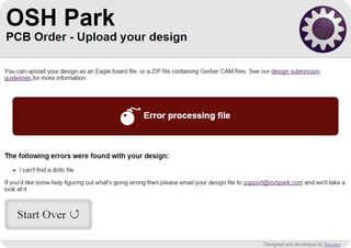
Usually this would consists of uploading board gerbers to OSH Park and getting payment sorted out. However, this time I was greeted with error: “I can’t find a drills file”. Mind you, this was expected since I really didn’t have a drill file, but unfortunately this wasn’t a warning I could skip. So I contacted support.

I really didn’t expect any quick answer since I raised ticket on December 31st after 16h PST. Surprisingly I got the solution almost immediately. It wasn’t possible to upload design without drills but Dan (yep, Laen doesn’t handle support any more) suggested a file with drill locations all falling outside of board. Their filtering process would then remove those as invalid and my drill-less board would be ready for manufacturing.

While this solution was acceptable for one-off job, it got me thinking whether there was something a bit more elegant and less error-prone if I create some bigger board in the future. To solve it properly I had to have a drill file without any drills. To the Excellon specification!

With a bit of testing, I got to the minimum of content that OSH Park parser would still consider a valid drill file. It is essentially just defining one drill tool, selecting it for work and then finishing script without ever drilling a hole:

M48
INCH
T01C0.0394
%
T01
T00
M30

Empty drill file is available for download.

Rectangular NFC Antenna Calculator

NFC coil example

For a project I had to calculate parameters needed to make nice rectangular PCB inductor for a NFC antenna. Since my search didn’t bear desired results, I decided to make my own.

Enjoy.

mm
mm
oz
mil
mil
 
mm
mm
mm
 
μH

Calculation is done per NXP’s AN1445.

FTDI - Best to Avoid?

Serial port ruled the hobby market when connecting custom electronics to a computer was needed. As USB became prevalent, instead of serial interface we got USB-to-UART chips. Most common ones were manufactured by Prolific and FTDI and they became defacto standard. I personally chose FTDI’s FT232RL for huge majority of my designs. Partly it was due to driver availability for almost any platform and partly due to my bad experience with Prolific’s PL-2303.

Mid October FTDI pushed new WHQL certified driver via Windows Update. For quite a few customers that meant death of their serial devices. And it wasn’t just a compatibility issue. Once some devices saw new driver they became unusable on other operating systems (yes, including Linux). For more information, there is a huge thread at EEVblog forum along with some other sources.

Story started when the FTDI engineering found a way to detect some (if not all) non-genuine chips reprogramming them in process. For all practical purposes any device containing fake, cloned or compatible chip became dead. You could boot into Linux and previously working device would refuse to cooperate. You could even move it to another computer (without driver update) and it still wouldn’t work. While change is reversible by the expert user, normal user would just assume device is dead.

Were they in the right to detect fake devices and not work with them? For fakes chips answer is most definitive yes. It is a bit of a gray area when it comes to the compatible chips that have no FTDI markings. But actually killing the end-user devices is taking “pirate” fight a step too far. I am not necessarily talking about legality of “bricking” devices; I am sure that we will see at least legal analysis if not a legal action due to this.

As it works currently, in hobby market, you almost never contact manufacturer directly. You typically go via third-party. Whether you get legitimate or counterfeited chips is mostly a function of price. But you can get a real chip for cheap (e.g. somebody selling unused stock) and you can get a fake for a full price. Yes, you are more likely to get a original if you deal with a big/official suppliers (e.g. DigiKey, RS, Farnell/Newark/Element 14/whatever-is-their-name-now) but they are pain to deal if you are from in “unsupported” country. And a dollar difference here or there might make a difference to a hobby user.

As you sell a few devices with everything looking peachy they all suddenly stop working. Devices start coming back and you need to issue refunds or give a new device with a genuine chip. In an ideal world, you would sue your supplier and recover your damages. In reality you just swallow the loss because having a day in court would cost much more (in both time and money) than what you can hope to win. Only thing you can do is to avoid troublesome chip in the future. Once burned twice shy.

Similar problem exists if you bought a hardware device with the purest intentions. Price was right, not too high, not too low, functionality was just right and device used a FTDI chip internally (e.g. quite a few Arduinos, some BusPirate versions, humble chip breakout, or even some boards I made). But device manufacturer either used fake part knowingly or they just got screwed. In former case device was happily working until suddenly unrelated driver update killed it. If device is new you might get a refund. But chances are that you’ll get nothing.

If you are doing more than a few devices chances are you’re probably outsourcing assembly to somebody else. Dealing with assembly is handful on the best of days and now suddenly you might have on your hands a bunch of devices that pass all possible tests on the assembly bench only to be bricked by the end-user’s computer. To anybody other than the biggest manufacturers this is a scenario from hell. You will need to replace quite a few devices with assembler claiming devices work on their end and that it is not their issue. Court may be your friend but money/time equation usually does not work out.

And it is not as this fixes issue of fake devices. Those making fakes will just adjust their firmware to behave as a real FTDI chip for this case and Whac-A-Mole starts anew. I personally see a much higher chance that some later driver update will accidentally kill some genuine chips rather than preventing cloning. Recognizing that problem, FTDI CEO did say “sorry” but with a side dish of “we’ll do something else less drastic next time”.

I will personally vote with my wallet until I see what next few months will bring in this FTDI saga.

PS: If you want to get away from the FTDI but you don’t want to rework your board, there is a Cypress CY7C65213-28PVXI. It is pretty much exact pinout (albeit without possibility of an external oscillator), supporting anything from Windows 98 onward, and at a lower cost.

PPS: Those prepared to change board can look at MCP2221.

PPPS: Yes, I am aware my actions are purely cosmetic since I only buy 20ish FTDI chips a year.

[2016-02-05: They’re at it again. This time not bricking, just messing with data output.]

How Much for the Shipping?

Illustration

One of the most common ways to interface a computer and custom electronics is still a serial port. Since 9-pin connectors are mostly thing of the past usual choice these days is an USB to serial bridge chip.

While I am usually relying on excellent FTDI’s FT232R, I am always open for a something new. Therefore I was click-happy when I saw Silicon Labs tweet about $5 evaluation kit of their CP2104.

I went forward only to be surprised at the shipping cost for a device that cannot be heavier than a few dekagrams. Cheapest shipping within United States was $26 - a way too much for this device especially when anyone, as a private person, can get a better deal from UPS. How come that company such as Silicon Labs cannot ship it cheaper? Answer is - they can.

Over-inflating shipping cost became popular on ebay as a way to seem really cheap. You decrease item cost and increase the shipping. Total amount you get is still the same but your offer stands out as the cheapest one. With time this way of pricing has spread to Amazon and essentially any site that allows you to set shipping cost.

Somebody from Silicon Labs wanted to be able to say they do cheap kits but without all the hurdle of actually being cheap. I call that lying, they call it marketing. :)