Sometime I have a need to convert byte to it’s hexadecimal representation. I did that plenty of times - you just call ToString or whichever function your favorite language has and byte ranging from 0 to 255 gets converted to two ASCII characters spanning familiar ‘0’ to ‘F’ range. If this code needs to be implemented in assembler for micro controller, things start to get more interesting.
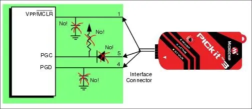
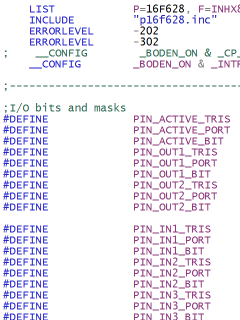
This version of code is implemented on both PIC16F628 and PIC16F690 (although code should work on almost any 8-bit PIC). Function is called TXD_HEX and source code is here:
TXD_HEX
    MOVWF       var_hex_in
    SWAPF       var_hex_in, W
    CALL        TXD_HEX_NIBBLE
    MOVFW       var_hex_in
TXD_HEX_NIBBLE
    ANDLW       0x0F
    ADDLW       '0'
    MOVWF       var_hex_out
    SUBLW       '9'
    BTFSC       STATUS, C
    GOTO        TXD_HEX_NIBBLE_DONE
    MOVFW       var_hex_out
    ADDLW       .7
    MOVWF       var_hex_out
TXD_HEX_NIBBLE_DONE
    MOVFW       var_hex_out
    CALL        TXD_BYTE
    RETURN
TXD_HEX
Upon entrance first thing we do is storing actual character that we need to transmit into var_hex_in. Since most operations work on W register (and thus overwrite it) it is handy to have it around.
Each byte must be encoded as two (hexadecimal) ASCII characters. It is best to show it with example of byte 11001001. Here we need to encode 1100 in first ASCII character and 1001 in second. Since most of numeric operations work only on low bits, we need to move first four bits (or nibble) to appropriate place. This is where SWAPF comes in handy since it will swap nibbles (result would be 10011100) and thus our data (1100) will be in proper place. Only thing left after that is actual conversion (in TXD_HEX_NIBBLE).
As soon as first byte is out we move original data back to our W register and use it (1001) for second visit into TXD_HEX_NIBBLE.
TXD_HEX_NIBBLE
Since this function works with lower data bits only (SWAPF ensures this) first step is to trim excess bits - ANDLW ensures that only lower four bits survive.
Those four bits are then “shifted” so value 0 moves to letter ‘0’. Value 15 (highest that we get) ends on letter ‘?’ (because there are some characters between ‘9’ and ‘A’) but we shall sort this later if needed.
Temporary subtraction (SUBLW) and checking whether we are still in positive range (BTFSC) ensures that TXD_HEX_NIBBLE_DONE gets called if our nibble has value between ‘0’ and ‘9’.
Values above 9 get moved for additional 7 places in order to align our original value 10 with letter ‘A’. After this we also continue with TXD_HEX_NIBBLE_DONE.
TXD_HEX_NIBBLE_DONE
This function just moves our stored hexadecimal value back in W register and then calls TXD_BYTE (not shown here) with hexadecimal ASCII in W register. Last RETURN goes back to next nibble (see CALL TXD_HEX_NIBBLE at very beginning) or, if second nibble is sent, goes back to original caller.
Prerequisites
Obvious one is to put byte that is to be encoded in W. This is just how I am used to, you might use separate variable for that if you fancy it better that way.
Important thing is to have TXD_BYTE function somewhere in your code. This function will do actual sending of each ASCII character. Datasheet for each particular PIC has example for this so I will not write it here.
You also need to define variables elsewhere in your program. Only two are needed (var_hex_in and var_hex_out) but do notice that you need to be switched to correct bank (with BANKSEL). Beauty of PICs and bank selection ensures that you need to put some thought in it. I usually just cram it in bank 0.
Enjoy hexadecimal.