How to Store Settings Without EEPROM
Having customizable setting in your PIC program is easy. Just define it as a constant and let XC8 handle everything else. If you need to change it during runtime there is bunch of code out there dealing with EEPROM access. But what if you want to store something in PIC without EEPROM?
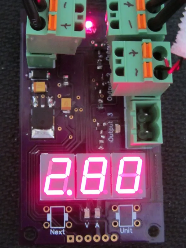
In my case I needed to store two settings: Counter and Unit. Hardware device was already built around PIC without EEPROM so there was no choice but to use self-programming feature that almost all newer PICs share.
Idea is simple. Reserve some space in program memory by making some data constant (e.g. const char mySetting = 3;). Every time you access this variable PIC will return what it had stored there at time of programming. Our trick is to change those values by reprogramming code as it runs.
First complication comes from fact that you cannot just write in flash willy-nilly. Before each write you need to erase whole block of (usually) 64 bytes. Unless you are willing to write very complicated code that also means that you will always need to occupy whole block regardless of how many bytes you want to actually store.
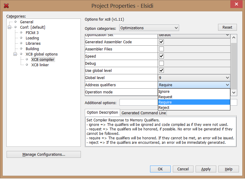
Second caveat is that you can only erase whole block. That means that you cannot let compiler decide upon location of your data. You must select fixed location and that might give you :0: warning: segment "__SETTINGS_PROGRAM_text" (200-23F) overlaps segment "intcode" (8-273). Fortunately solution is really easy - just move your constant somewhere else. Of course that implies that you have enough free flash memory laying around.
Third issue might be that this operation typically takes few milliseconds which is ages in microcontroller terms. To make things worse interrupts must be disabled during almost all that time. Any precise time keeping is out of question.
However, if you wiggle your way around all these obstacles, you get nice storage for times when you just cannot afford EEPROM for one reason or another.
Full source follows:
#define _SETTINGS_FLASH_RAW { 0, 0, 0, 0, 0, 0, 0, 0, 0, 0, 0, 0, 0, 0, 0, 0, 0, 0, 0, 0, 0, 0, 0, 0, 0, 0, 0, 0, 0, 0, 0, 0, 0, 0, 0, 0, 0, 0, 0, 0, 0, 0, 0, 0, 0, 0, 0, 0, 0, 0, 0, 0, 0, 0, 0, 0, 0, 0, 0, 0, 0, 0, 0, 0 } //reserving space because erase block is block 32-word (64-bytes)
#define _SETTINGS_FLASH_LOCATION 0x0400

#define _SETTINGS_STORE_EMPTY { 0, 0 }
#define _SETTINGS_STORE_BYTES 2

#define _SETTINGS_REENABLE_GIE_AFTER_WRITE     1

const unsigned char _SETTINGS_PROGRAM[] @ _SETTINGS_FLASH_LOCATION = _SETTINGS_FLASH_RAW;

void _settings_write(int index, unsigned char data) {
    unsigned char newProgram[] = _SETTINGS_STORE_EMPTY;
    for (int i=0; i<_SETTINGS_STORE_BYTES; i++) {
        newProgram[i] = _SETTINGS_PROGRAM[i];
    }
    newProgram[index] = data;

    GIE = 0;

    EEPGD = 1; //point to Flash program memory
    CFGS = 0; //access Flash program memory
    WREN = 1; //enable write to memory

    TBLPTR = _SETTINGS_FLASH_LOCATION;
    FREE = 1; //enable block Erase operation
    #asm //erase block
        MOVLW 55h
        MOVWF EECON2 ; write 55h
        MOVLW 0AAh
        MOVWF EECON2 ; write 0AAh
    #endasm
    WR = 1; //start erase (CPU stall)

    TBLPTR = _SETTINGS_FLASH_LOCATION;
    for (int i=0; i<_SETTINGS_STORE_BYTES; i++) {
        TABLAT = newProgram[i];
        asm("TBLWT*+");
        #asm
            MOVLW 55h
            MOVWF EECON2 ; write 55h
            MOVLW 0AAh
            MOVWF EECON2 ; write 0AAh
        #endasm
        WR = 1; //start program (CPU stall)
    }
    WREN = 0; //disable write to memory

    if (_SETTINGS_REENABLE_GIE_AFTER_WRITE) { GIE = 1; }
}


#define _SETTINGS_INDEX_COUNTER  0

char  settings_getCounter() {
    return _SETTINGS_PROGRAM[_SETTINGS_INDEX_COUNTER];
}

void settings_setCounter(char data) {
    _settings_write(_SETTINGS_INDEX_COUNTER, data);
}


#define _SETTINGS_INDEX_UNIT 1

char  settings_getUnit() {
    return _SETTINGS_PROGRAM[_SETTINGS_INDEX_UNIT] % 3;
}

void settings_setUnit(char data) {
    _settings_write(_SETTINGS_INDEX_UNIT, data);
}
It would be best if you would keep this code in separate file (e.g. settings.h) and just include it from your main program file instead of pasting all this directly.
PS: If your program does not use interrupts change _SETTINGS_REENABLE_GIE_AFTER_WRITE to 0.
PPS: Do notice that flash memory was not intended as this kind of storage medium. Writing is much slower than EEPROM (because of erase) and endurance is much lower. Use it only in dire straits and be gentle.
PPS: This code is for PIC18F* series of micro-controllers. Same general principle works on PIC16F* but names of some registers might differ and additional NOPs might be required. Do check instruction manual.