Bad things happen when programmer finds a soldering iron

The Cost of CyberCard

After publishing text about the CyberCard project I got the question from a friend. Wasn’t it cheaper to buy Jeff Mayes’ interface driver then to build my own?

Answer is yes - at $30 that board is cheap. But that’s not all. Even the original RMCARD205 at $150 is cheaper than what I spent.

First of all, there were 4 revisions. The first revision was a bit too large. Manually filing PCB did the trick for the troubleshooting but I wanted to have revision B with the correct width. While width was now correct, I accidentally shortened it a bit. And yes, this brought me to the third revision. For that revision I also changed MCP2221A to SOIC package. It wasn’t strictly necessary but I figured having all three ICs in SOIC looked nicer than having different package styles on the same board. The last revision D was just a bit more fiddling with design without any major change. Yes, there were some other changes but this was a gist of it.

Considering each revision was around $25 in PCB cost (OSHPark) and I spent about $50 in parts for them, project was more expensive than official RMCARD205 even without accounting for my time. Since the first version was actually working, you can view all the time and money spent afterward as wasted.

But I disagree. From the moment I started working on it I knew it would end more expensive than the original part. Even for the first board I spent more money in PCB and parts than what Jeff’s adapter would cost with shipping. I found this board to be the perfect project: it would result in something useful, it was simple enough that I could work with it whenever I had some spare time, cheap enough that it wouldn’t break the bank, and an excellent chance to setup PIC16F1454 as an USB device.

I was eyeing PIC16F1454 for a few years now (I still have sample from Microchip from when it was originally announced) but I never got around to. When I first started with the board design I noticed MCP2221A USB-to-serial bridge was compatible with 16F1454’s footprint. If I was a betting man, I would have said that MCP2221A was nothing other than PIC16F1454 with the custom code. This project gave me a reason to get into this interesting PIC and do some USB programming.

I actually paid not for the final board - no matter how well it works. I paid a good money to keep me entertained and to fill my free time. And it was worth every penny.

Connecting to CyberPower OR500LCDRM1U UPS Serial Port

Illustration

To keep my file server and networking equipment running a bit longer in the case of power outage, I have them connected to CyberPower OR500LCDRM1U UPS. It’s a nice enough 1U UPS but with a major issue - no USB connection.

Well, technically there is an USB connection but it doesn’t work under anything else than Windows. If you want it working under Unix, the only option is RMCARD205, optional network module upward of $150. Essentially doubling the price of UPS.

And it’s those internal connections Jeff Mayes took advantage of for a simple serial interface. If the only thing you want is a serial interface, you might as well go with his interface driver as price is really reasonable.

However, his boards require you to either have a serial port or to have an USB-to-serial cable. What I wanted was direct USB connection. Since there was nothing out there, I decided to roll my own.

Since I had an UPS locally, it was easy enough to get physical dimensions. Unfortunately just measuring them wasn’t sufficient as they narrow as you go deeper so my first assumption of 3.1x1.7 inches was a bit off. Due to that and bottom connector that was a bit shallower then expected, the final board dimensions were more like 71x43 mm. It took a bit of probing to find the 4 signals I needed were grouped together with GND and RX on the bottom while TX and 12 V were on the top.

Connecting the appropriate serial connections to UART-to-USB converter like MCP2221A was a minimum required but I felt a bit queasy about connecting it directly to my computer. Therefore I decided to isolate the UPS interface from the computer. For this purpose I used Si8621 digital isolator offering 2,500 V isolation which was probably an overkill but allowed me to sleep better.

The last physical piece needed was a cover for card to avoid having a large opening in the back of my rack. While risk of anything getting inside is reasonably low, making a 3D printed cover was easy enough. It took a few tries to get cover design right in TinkerCAD but it avoided having a gaping hole.

If you are interested in making one for yourself, check project page for all the files.

Easy Type-C, Finally

It has been a while since USB Type-C became popular but I still avoided it for my hobby designs. It wasn’t due to its performance, oh no - performance was much better than what I needed. You see, I still use USB 2.0 for literally all my electronics projects. While not fast in the grand scheme of USB, it’s plenty fast for serial communication and that’s what I end up designing my gadgets around 90% of the time. My issues with the connector were due to soldering. Hand-soldering, to be precise.

Most of the type-C receptacle designs are of surface-mount kind. On its own that’s not an issue - I’ve hand-soldered my share of finicky narrow pitch ICs. Issue is the location of 24 pins that are needed. While 12 pins are almost reachable by a thin soldering iron, the other 12 pins are usually under the device. Not an issue if you are making them professionally or even in an oven but impossibility for soldering by hand.

And no, you cannot solder just one side of connector and be compliant. It doesn’t matter if you’re only interested in USB 2.0 as I was - you still need to connect both sides as you need to connect 5.1K resistor for device to be properly recognized. And yes, even if you fail to do that it will work with the type-A to type-C cable. It will sometimes work even with the type-C to type-C. However, things that happen only sometimes have a nasty habit of happening at the most unfortunate time.

Connectors that used a combination of through-hole design and surface-mount pads looked promising on the paper. The unreachable pads underneath were converted to pins and soldering problem got solved. Unfortunately, a lot of such connectors had a shield over the rear pads. Now rear pads became a problem. I did find a few with more open space that were easier to hand-solder but at a pricey $3.

But finally, I found the type-C connector that suits my use case perfectly - USB4085-GF-A. It’s an USB 2.0 connector that allows connection to 16 out of 24 type-C pins. The sacrificed pins mean that you won’t ever be able to use it with the high-speed devices (thus 2.0 moniker). However, the pins that remain include not only all the standard USB 2.0 power and data connections but also CC1 and CC2. These two pins are really important if you want your device to be part of the type-C universe and pull 1.5 A of current. The only thing needed in addition to the old type-A designs is two 5.1K pull-down resistors on each of those pins and you’re golden.

Mind you, the connector is not perfect. At $1.50 it’s a bit pricey but not excessively so. If you are using the standard 1.6 mm PCB, you will need to take a great care to position it flush in order for short pins to even reach to the other side. Hole spacing means you will need to use 6/6 PCB manufacturing which, while often supported, is still a bit less common than bog-standard 8/8. But these are all minor issues and hand-soldering is a breeze.

And despite all this goodness, I only used it for a few test contraptions and not in any of my proper projects. This is due to its biggest drawback - there is only one manufacturer and, outside of my initial purchase, they are pretty much on backorder the whole time. Even at the time of this writing, the quantity is 0 on DigiKey.

Once this connector becomes more available, I am looking forward to using it.


PS: For those wanting to have type-C plug directly on the board, there is a Molex 105444-0001. Just don’t forget to order 0.80 mm PCB.

PPS: For the 90° type-C connector, KUSBX-SL-CS1N14-B looks promising as it also allows connection to both CC1 and CC2 - a necessity for the proper type-C device. I haven’t tried it myself though.

Serial Number In Intel Hex - Bash Edition

When creating USB devices having an unique serial number for each is quite important. Yes, stuff will work with duplicate (or missing) serial number but you might notice Windows will get confused. With the serial devices the most noticeable effect will be a different port assignment on each plug. Not a breaking deal but a bit annoying.

The easiest way to deal with this is having a dummy serial number in code and then using post-build action to change it in the final Intel hex file. For TmpUsb project I even created a script to do exactly this. However, that script was written in PowerShell which until recently (March 2020) didn’t work on Linux and it definitely doesn’t come installed there by default. This and a few other reasons were why I decided to rewrite this in Bash for my CyberCard project.

The first step is setting up the serial number. The most crucial step here is __at macro that will ensure serial number is always at a predictable location. For my example, I selected location close to the end of addressable space (0x1F00). One could use special characters here but I would highly advise to have a valid USB serial number just in case script fails. That means at least 12 alphanumeric characters but I always go for numbers-only as it makes script a bit easier.

//Serial string descriptor
const struct{uint8_t bLength;uint8_t bDscType;uint16_t string[13];}sd003 ^^__at(0x1F00)^^={
    sizeof(sd003),USB_DESCRIPTOR_STRING, {
        '1','9','7','9','0','1','2','8','1','8','1','5','0'
    }};

The final Intel hex file location will end up multiplied by 2 and thus at offset 0x3E00 further shifted by 4 hexadecimal characters. Script then needs to replace every 4th hexadecimal byte up to the count of 13 in my case (as my serial number is 13 digits long).

The only task remaining is calling it once project is done building. Previously I would do this using project properties dialog (Project Properties, Conf, Building, Execute this line after build) but that proved to be an issue if you want to compile on both Windows and Linux. While Linux setup was quite straightforward, on Windows it would get confused if you have any Linux-based toolset installed (e.g. Git Bash) and throw an error:

"User defined post-build step: [update-serial.sh]"
nbproject/Makefile-default.mk:105: recipe for target '.build-conf' failed
make[1]: Leaving directory 'Q:/Projects/Electronics/CyberCard/Firmware/Source'
nbproject/Makefile-impl.mk:39: recipe for target '.build-impl' failed
process_begin: CreateProcess(NULL, bash Q:\Projects\Electronics\CyberCard\Firmware\Source\update-serial.sh, ...) failed.
make (e=2): The system cannot find the file specified.

One workaround was to simply wrap call to this script in .cmd (or .bat) file but that would cause issues when compiling under Linux. Only if there was a way to execute one command for Windows and another one when running on Linux… Cue the Makefile.

While you cannot differentiate OS from GUI, you can go and edit MPLAB project Makefile directly. There we can point toward .cmd on Windows and toward .sh when running on Linux.

.build-post: .build-impl
# Add your post 'build' code here...
ifeq ($(OS),Windows_NT)
        update-serial.cmd
else
        ./update-serial.sh
endif

All that is left is actually placing the script(s) in the same directory the Makefile is situated (download here) and you’re good assuming you defined serial number as I did. If you didn’t, just adjust LOCATIONS variable inside.


PS: This assumes you have Git (or some other bash-capable environment) installed in Windows.

PPS: Don’t forget to use <Tab> in Makefile for indentation. Spaces won’t do here.

ResetBox

Illustration

It all started with an itch to scratch. My modem occasionally misbehaves and needs a reboot. Unfortunately, I have it mounted way back in the 19" rack and accessing it requires removing back panel. And no, I cannot easily unplug it’s connected to UPS and wires are all tucked in the back. What I needed was a button in one of rack spacers allowing for reboot of equipment in the back.

Since I couldn’t find something like this readily available, I decided to build it.

First I enumerated all the equipment I have. One modem (12 V), one NUC (19 V), and finally two wireless access points (48 V). I was at crossroads. As voltage range is quite wide I had to choose if I want to make device work of specific voltage (cheaper) or to have a single device covering all the bases (more expensive). While going cheaper was tempting, I decided to go with wide input after all. It meant I can design thing only once and use it later for some other project without having to check voltage rating each time.

This decision also made me select DC-DC converter module. Making my own wide range converter would be possible but getting it just right would take annoyingly long time and actual cost wouldn’t be much lower. Yes, at $5 R-78HE5.0-0.3 is not cheap but it’s simplicity is worth every penny. If I ever decided to produce this box in bigger quantities, this would probably be the first thing to go in order to lower expenses and simplify design.

While not necessarily mandatory, I also opted to include EMC filter for DC-DC converter. Considering low currents it’s probably an overkill but I really didn’t want to find out later that I’m spraying too much noise around my rack. Design improvement would be to either remove filter all together (probably possible due to low current requirements) or make it much simpler and hopefully omitting SMD inductor. I hate to solder that stuff.

It took me a while to find a button as I wanted momentary switch with LED (excellent for giving status) and it had to look nice in rack. I finally found Adafruit’s S 560. This button is awesome in person.

To connect button, I selected JST S3B-XH. I needed the minimum of three wires (GND, LED, and switch input) and I already had bunch of premade cables made in the course of another project. If I had only this project to worry about, I would probably select 4-wire connector as it would make soldering a bit easier. Not it’s too hard now - just wire GND to both LED and NC input and you’re golden.

Voltage connector choice was extremely easy as literally all devices I wanted to control already used barrel connector. Since 2.1 mm barrel had became a defacto standard for network cameras, this also meant I could count on connecting it all with factory cables making the whole setup a bit nicer.

Speaking of which, I mulled long time about whether I should support only barrel setup with positive voltage on tip and negative voltage on sleeve or the inverse one too. All network devices I ever owned have positive tip. However, I decided to allow negative tip setup to. I am 95% sure this was completely unnecessary precaution but at least I don’t need to worry about it.

As far as saving money goes, supporting only positive tip barrel connectors, would allow me to remove diode bridge on input and allow me to replace mechanical relay with MOSTFET. As I’m making only 3 devices, for now I value flexibility the most. But decision to include these still bothers me a bit.

Housing hardware fell to Hammond 1593KBK. This is a reasonably sized and more important reasonably priced case with side panels. While I usually replace such panels with custom PCB with cutouts in place of connectors, this time I opted for 3D printed version. It’s definitely cheaper than PCB but it does require you to have printer. And no, it’s not as nice as PCB panel but it looks good enough - especially since device will sit in the back of the rack.

Lastly, I had to select microprocessor that would handle all logic. As most of my devices, I simply went with selecting Microchip’s part. I needed two outputs (LED and relay) and a single input (switch). In order to avoid complications, I like to keep programming lines separate too (MCLR, PGD, and PGC). Yes, you can share these lines with logic if you’re careful but having them reserved is one way to make sure. Once you include power supply, there is variety of 8-pin microcontrollers to chose from.

Finally I went with PIC12F1501-I/SN. It has 8 pins which is what we needed. SOIC package makes it easy to solder and internal oscillator minimizes extra components needed.

Code running on chip is as easy as it gets. What follows is the main loop.

void main(void) {
    io_led_on();
    while(true) {
        if (io_switch()) {
            if (debounceCounter &lt; DEBOUNCE_MAX) {
                debounceCounter++;
            } else {
                intensityCounter++;
                if ((intensityCounter % 8) == 0) { io_led_on(); } else { io_led_off(); }
            }
        } else {
            if (debounceCounter == DEBOUNCE_MAX) {
                io_relay_on();
                for (int i = 0; i &lt; RESET_COUNTER; i++) {
                    io_led_on(); wait_short();
                    io_led_off(); wait_short();
                }
                io_relay_off();
            }
            io_led_on()
            debounceCounter = 0;
        }
    }
}

If button is pressed, counter (debounceCounter variable) gets increased while button is pressed and until it reaches maximum. Side effect of handling counter like this is automatic debouncing and making sure short, accidental, swipes don’t activate reboot functionality. Once at maximum, counter stops and we dim the LED so user knows reboot will follow once button is depressed. Dimming is actually done by poor man’s PWM - just turn LED manually on 1/8 of interval (when counter is divisible by 8).

Second path executes only when the button is not pressed. If debounce counter is at maximum, a simple reset sequence starts. Here we disconnect relay (ironically by turning it on as it’s normally-connected setup) and LED blinks for 4 seconds. Then we turn relay back off so that power returns to the device.

It’s probably the simplest code I’ve written in quite a while.

If you want to check it a bit more, feel free to look up both board and code at GitHub.

Why You Should Update GPS Firmware

Illustration

Assuming you survived the great GPS rollover, you might wonder if updating your GPS firmware makes any sense at all. It’s obvious you might want new maps. But firmware? Why do you need a new one if everything works just fine.

Real answer is that you probably need not bother. Again, assuming everything works fine, there is no navigation reason for firmware upgrade. Navigation will work equally well whether you have fresh firmware or one that’s a few years old.

However, if you care about time keeping, you will definitely need to update your GPS once in a while. And it’s not because of rollover - that issue is sorted now with the new 13-bit week counter and it’s up to your grandchildren to bother with that. Nope, it’s darn leap seconds.

Leap seconds were created to account for uneven rotation of this big rock we call Earth. As such they are currently beyond our capability to calculate in advance. Once in a while astronomers look upon the skies and decide if leap second is needed. One cannot know in advance when this will happen.

AS GPS time has no concept of a leap second, firmware is what adjusts GPS time to UTC and then later to time zones we all deal with. Guess what, if you have old firmware, your GPS will adjust wrongly and thus something you believe to be a correct time will be off by a second or two (or 27 if you were really lazy).

I know it’s not a breaking deal for a vast majority of population but I simply find it rather unnerving that you would intentionally make your GPS show the wrong time.

Update darn firmware to avoid having your existence out of sync with rest of the world. :)

El-Cheapo Power Supply Noise Measurement

If you are not doing power supply measurements every day, you probably don’t have any specialized probe for it. At best you might be using two probes and math channels to get a cheap differential-like probe as the only thing needed for this is your standard probes and a pair of pass-through 50 Ω terminators. Dave went over it on EEVBlog channel better than I ever could.

While this approach might not be perfect, it has advantage of a decent result with minimum parts needed. Assuming you already have the probes, only other parts needed are pass-through 50 Ω terminators that come in handy for other stuff too. If you are lucky, your scope might even have them built-in.

Due to low cost and ease of measurement I actually prefer it to more common single-ended measurements with short ground spring. Not only I find probing with two hands easier than dealing with springy ground wire but it also alleviates the need to worry as much about noise sources. With advent of switched LED lightning single-ended measurements just got too annoying.

Disadvantage, beside the precision, is that all your measurements need scaling as your probes and termination resistor make a voltage divider. Since we already know one side of voltage divider (50 Ω terminator), we need to measure probe’s resistance. From tip to BNC connector that will be in a few hundreds ohms range. Using the voltage divider formula, we get the ratio (for example I measured about 360 Ω):

ratio = (Rprobe + 50) / 50 = (360 + 50) / 50 = 8.2

While simply multiplying by ratio resulting numbers is not too much of a hassle and you could be done here, quite a few oscilloscopes will allow you to create a custom probe. As I usually use PicoTech 2206B, I will explain how to configure custom probe in PicoScope 6 so our on-screen result is already scaled correctly.

In Tools menu the first entry leads to Custom Probes window. There clicking on New Probe will start a wizard dialog. We use the standard volts unit and a linear equation. Our precalculated scaling ratio (7.6 in my case) goes under gradient and offset stays 0. Automatic range management is fine but software frequency filter we set to 20 MHz as PicoScope 2000-series has no hardware bandwidth selection. After naming the probe we can now select it in channel’s configuration.

When dealing with the “standard” probes, be aware that most x1 probes have around 10 MHz bandwidth. As power supply noise is usually measured with 20 MHz bandwidth limit this is something to be aware of. However, the whole measurement setup is on a cheap side and this will rarely be a deal breaker. Yes, you might not see the best fidelity but you’re gonna be in the ballpark regardless.

Further more, we are not interested in the DC component. If oscilloscope supports it, use AC coupling as we’re not interested in DC values - only noise. This will allow you to use all ADC bits for signal you want to see. If oscilloscope supports only DC coupling, you won’t be able to see much as, at ±5V, your 8 bits give you only 40 mV resolution and it goes worse from there. Unless you can get your analog offset configured (unlikely if your scope is so low end that AC coupling is unavailable), you can forget about any meaningful measurement.

Those doing it on cheap can check $140 PicoScope 2204A as it does support AC coupling. For example, assuming 100 mV range, you get quite adequate 0.4 mV resolution. As you go up in model selection you will get better bandwidth and bigger sample buffer but I would think even this works well for what we can get with this testing setup.

And I am mentioning PicoScope here specifically as other cheap scopes (whether PC-based or in MP3 player case) often don’t have AC coupling and lie about bandwidth on a grand scale at a comparable price. While you can get around missing AC coupling by placing capacitor in series, it is much harder to work around bandwidth restrictions and a missing analog frontend. PicoScope is not perfect (and it cannot be at that price point) but they don’t lie about their capabilities and their PC software is the best I’ve seen.

That aside, we’re not done yet. To see our “differential” signal noise, we have one more step. Under Tools there is an option called Math Channels. Here we can select already predefined A-B function and finally we can see the noise in all its glory.

PS: To automate measurements a bit, you can use Measurements, Add Measurement. Selecting A-B as a measurement channel will allow you to add both peak-to-peak and AC RMS as the most useful values.

PPS: The lowest PicoScope model where you can do these measurement comfortably is $350 2206B with 32 MS buffer. Lower models have only either 8 kS ($140 2204A) or 16kS ($225 2205A) making any analysis a bit annoying.

PPPS: Great thing about using PicoScope for measuring power supply is that it can be easily isolated. Just disconnect laptop from power supply and your USB (and thus PicoScope) is floating. :)

CAN Bus Decoding Using PicoScope

Illustration

When it comes to CAN bus protocol decoding, beating PicoScope is hard considering that even the cheapest 2000 series member has full support for it. Converting such scope to one with the floating ground is as easy as unplugging your laptop (or running your desktop of an UPS’ battery). However, there are a few issues you might want to avoid.

The very first step would be to properly trigger on the CAN bus message. Reasons for this are twofold. If there is any issue with your signal, this will allow you to catch it early so you can sort out basic electrical stuff before going on the higher level. Secondly, reliable triggering will help software decoder properly detect message start.

While exact trigger level might depend on the exact use case, in 95% of cases we are talking of 5V differential signal. Roughly speaking, your CAN L (low) signal will be either at 2.5 V or 0 V logical level and your CAN H (high) signal will be at either 2.5 V or 5 V level. Since signal between those two lines is mirrored, you only need to probe one of those two lines. I usually select L but that’s just because I already have cable made for it. All instructions are essentially the same whichever polarity you select. Good starting trigger level for low line is 2 V (3 V for high line). If your resting signal is further away from 2.5 V that would either point to termination issue or gross impedance mismatch and you should sort “electricals” first before continuing further.

Illustration

I like to set pre-trigger level to 5% as it allows me to use most of the screen for actual signal. To receive the maximum screen real estate you might be tempted to use 0% pre-triggering but I find seeing a bit of signal before my CAN message does help if you have a busy bus. Even better, this also allows you to ignore trigger edge setting completely (should be falling for low line).

Only once you can reliably catch your CAN signals, you can add serial decoder - Tools / Serial Decoding / Create / CAN. After selecting channel with your signal (named Data on this form), you will reap the benefits of getting triggers right. First and foremost, you should have bitrate set correctly as soon as channel is selected. More over, your threshold level should be automatically calculated from the signal. Yes, you can manually set it to 2 V but Murphy says you’ll forget it and then be confused as why decoding has errors or even misses a message completely. Lastly, you select High or Low setting appropriately depending on the line you are probing.

Congratulations! If all went good, you have just successfully decoded CAN bus message.

Ideal Multimeter

Illustration

If you are into electronics, probably the first test device you’ll own will be a multimeter. Not only you can get it for dirt cheap - my first multimeter was less than $10 in today’s money - but you can also do a lot in digital electronics with multimeter alone.

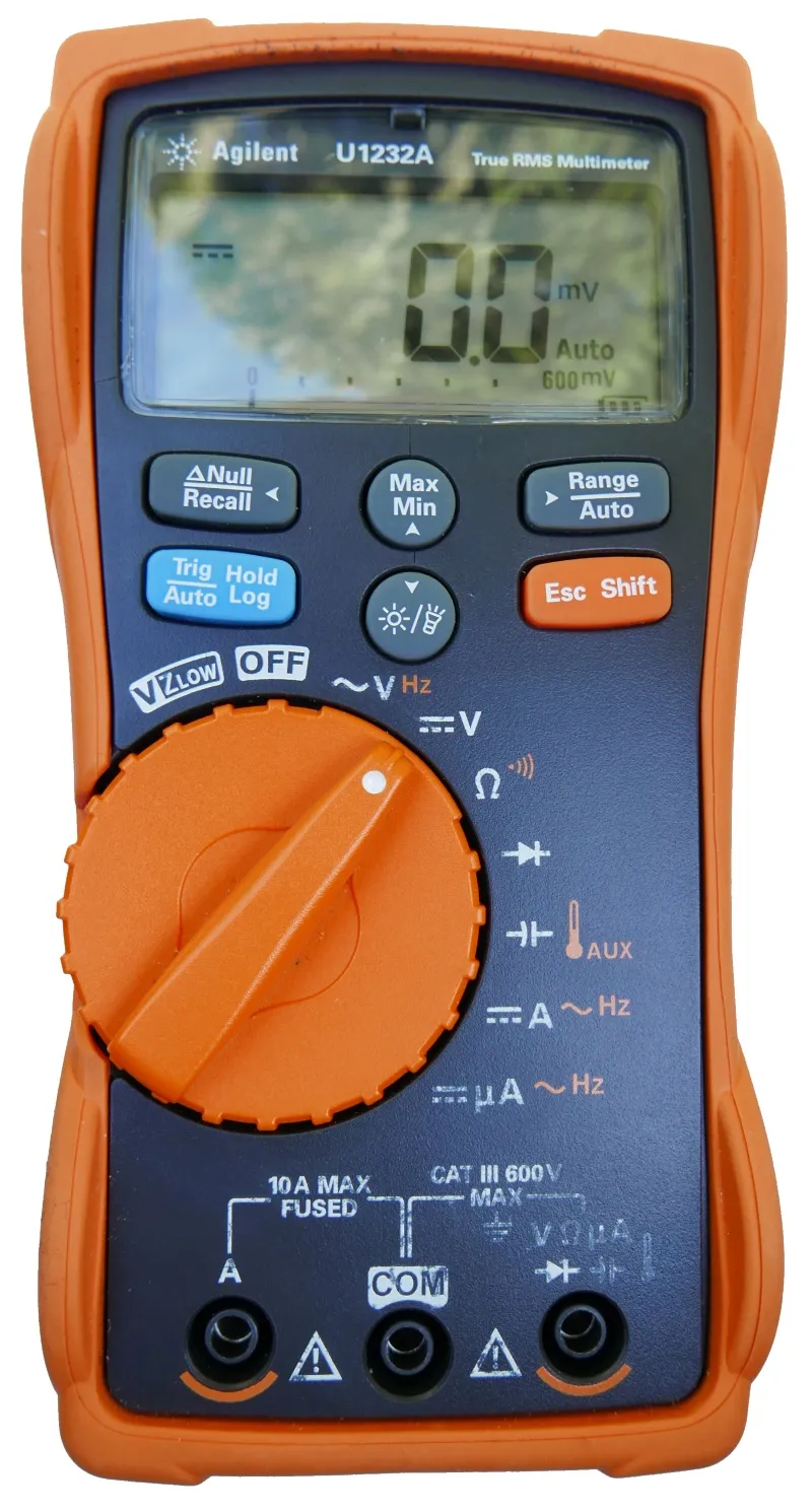
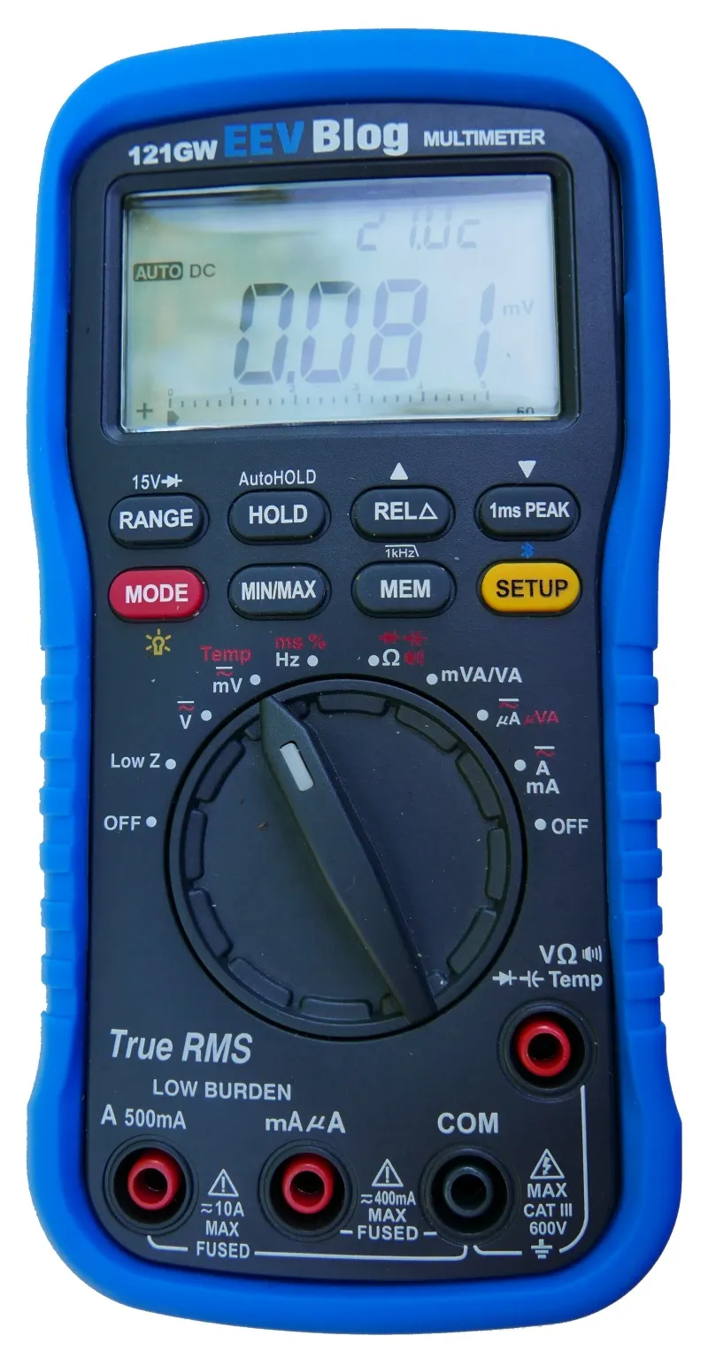
As I pawed my road to electronics with quite a few good and bad multimeters, I want to share my thoughts on what is important for a decent general purpose multimeter. I will stick to Agilent/Keysight U1232A and EEVBlog 121GW for most of my comparisons as these are two multimeters I use these days. However, principles are general and can be applied to any multimeter.

The very first thing I need of multimeter is to be safe. When I just started with electronics I didn’t care about that because I worked with low DC voltages only. However, sooner or later I would measure something on 240 V line. And not all multimeters would survive - some failing spectacularly. Having kids of curious age I like to have all my meters CAT rated and UL listed. And most of good meters will not die even if you do something utterly stupid like connecting to line voltage while in current range. Higher cost does offer higher survivability.

The next thing I find very important is speed. Having a high digit count is nice but it usually comes at the cost of speed. I find that 6000 count on my Agilent is much more comfortable for general measurement than 50000 counts EEVBlog has to offer. Yes, high digit count is important for certain scenarios and it’s not too bad to have one such meter available. But, if I had to choose one multimeter, I would go for a faster one. That said, don’t go under 6000 counts.

Illustration

In regards to speed, a special attention should be shown toward continuity check. Regardless of the display update speed, continuity tester must be fast and latched. Even the most minute contact between probes has to result in the (low volume, please) beep or flash. While most people prefer beep, I find backlight flash really great but that might be due to most of my work taking place during night when flash is easily visible and laud noises are not really desired. Speaking of flash, I love option to turn backlight with a single button. If you ask me, I would set all my multimeters to have backlight by default - battery life be damned - but I will be OK if I can turn light on easily.

I prefer when each measurement is a separate selection on a range switch as it makes switching between them a breeze. Multimeters with a lot of options tend to have just a few ranges but with Mode button switching between them. 121GW is specially nasty in this area as, not only it requires mode button but it also remembers the last mode selected. While this sounds like a good idea, it ensures that I need to check every time by looking onto display (that requires long press for backlight) before doing any work. This alone is probably the major reason why my Agilent sees much more use despite 121GW having more functionality and better specs.

Speaking about more functionality, I found 121GW’s mV range a real gem. If your multimeter gives you decent resolution it can pretty much substitute measuring current altogether. Just measure voltage drop over a resistor (or fuse) and you have all that’s needed to calculate current. Much easier than switching to current range and inserting multimeter into the circuit. Yes, this won’t work if you need precise and/or low-current measurement, but it works well to get ballpark figure and that’s often all that’s needed anyhow.

And order of measurements on the range switch is equally important. I prefer my order to be Low-Z voltage measurement, Off, DC voltage, AC voltage, other voltage related measurements, current, and finally the second off position. While this does prevent me from easily turning off multimeter by just moving switch into the far left position, it enables me to setup all on board and go into voltage measurement directly without traveling through Low-Z mode. While I love low-Z mode, I do not like when I have to go over it from off position (Agilent did this beautifully). Speaking of low-Z, idiotic restrictions like 12V minimum voltage for it to work 121GW has make it more nuisance than an useful range.

Illustration

If you are into temperature measurement, you will want support for standard K-type probes. Agilent here fails miserably as it requires special adapter to do it. My personal opinion is that, if any special adapter is required for measurement, that functionality might as well not exist.

Functionality I found awesome but it’s rarely implemented these days is a simple frequency counter. Yes, both U1232A and 121GW can measure frequency but range is laughably small (up to 100 kHz and 1 MHz respectively). When you deal with PWM circuits or you just want to check clock lines, a decent frequency measurement (like UT71C has - up to 40+ MHz) means you don’t need to pull out the scope most of the time.

Having the low burden voltage is an excellent thing in theory as it can mean a difference between being able to measure circuit’s current or not. In practice it depends on your use case. For me, working on 3.3V and 5V circuits, there is more than enough margin to handle any drop multimeter brings in.

Diode measurement should be a separate range so LED (or any other diode) polarity can be tested without much effort. If you are dealing with LEDs a lot, investing in multimeter that supports higher test voltage (like 15V on 121GW) does come in handy.

Other features worth mentioning include True RMS and auto-hold functionality. I found that not having either is not a breaking deal but they do come in useful once in a while.

Illustration

I do require support for either AA or AAA batteries in any multimeter I use. Not only 9V has generally inferior capacity but it’s also something I don’t ever have when I need it. There is simply no justification this day and age why standard batteries shouldn’t be used. And battery compartment should have a captive screw unless you want to spend 15 minutes searching for it every time you change the batteries.

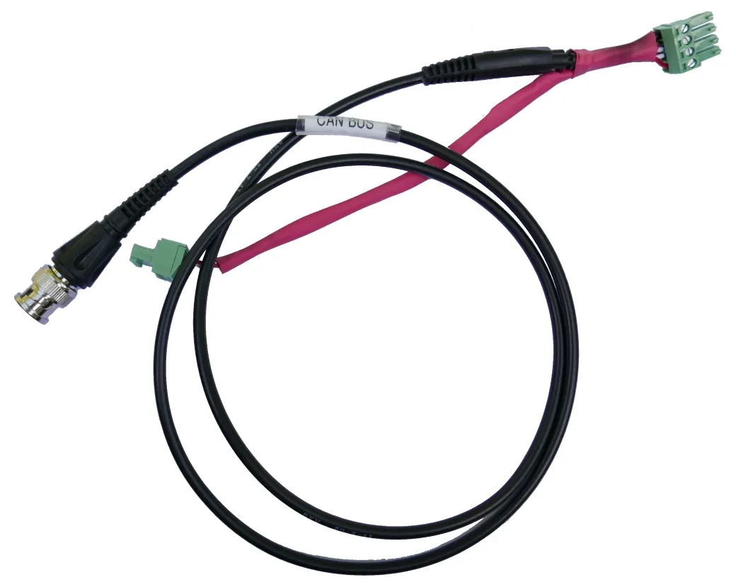
Every decent multimeter will have a way of connecting to the computer for logging purposes. While bluetooth seems like a good idea, I found it lacking in practice as I would often find something would go wrong with it overnight. A nice physical cable is my preferred solution here.

In regards to the probes I find silicone is a must as stiff probe cables will be a hindrance. Tips have to be sharp and ideally their CAT III/IV insulation should be removable. Fully insulated probe is fine when dealing with high voltages or narrow spaces but often more exposed metal makes for easier measurement.

Unfortunately, finding the multimeter with all these features is hard if not impossible. Every multimeter - regarless of the price range - will have something missing. However, with two multimeters you can come darn close.

PS: Notice I haven’t spoke about precision at all as needs are highly dependent on the exact use case. For me 1% on DC is OK and this is something easily found in any decent multimeters.

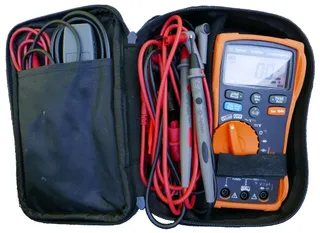
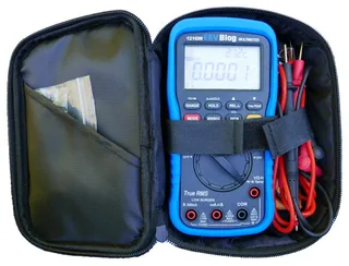
PPS: One enjoyable thing you cannot really know until you see it also how multimeter fits in its carry case. Agilent is perfect here as you have range switch, all buttons, and probe holes reachable without ever getting it out.

Random on 8-bit PIC

When dealing with 8-bit microcontrollers one doesn’t always have all facilities taken for granted on a computer. One such example is a simple random number. While all computers can easily provide you with random number at will, unless you have a heavily specialized PIC, real random numbers are out of your reach. However, there is a way to get sufficiently close to make it work for most non-cryptographic purposes.

The answer is in linear-feedback shift registers. Assuming polynomials are carefully chosen, it is relatively easy to get non-repeating 255 byte sequences on 8-bit PIC. Yes, they are not random but for the most purposes they are random enough.

There are many types of LFSRs, Fibonacci’s being the most famous and probably the one implemented most often due to its simple hardware structure. However, for the PIC device, Galois has similar enough properties with a much simpler software structure.

General Galois function might looks like this:

#define GALOIS_POLYNOMIAL 0b11010100; //x^8+x^7+x^5+x^3+1
uint8_t randomState;

uint8_t getRandomByte() {
    unsigned bit = randomState & 0x01;
    randomState >>= 1;
    if (bit) { randomState ^= GALOIS_POLYNOMIAL; }
    return randomState;
}

This function essentially takes whatever data has in previous step and, using one of the maximum sequence length polynomials, calculates the next random byte. However, if you run it as such you might or might not get anything other than 0. Why? Well, pesky sequence has one blind spot - number 0. You can get any 255 byte sequence assuming it does not contain 0. If data becomes 0, it will stay 0.

Knowing this, one might be tempted to simply initialize data to some number and call it a day. Indeed, that would work for many applications that use 8-bit PIC. However, there are two things to have in mind: sequence will repeat every 255 bytes and random number sequence will be exactly the same on every startup.

To deal with the issue of repeating sequences, we need a counter that will simply reset the sequence after it “runs out of bytes”. As LFSR “circles” back to the original value after going thru all permutations (assuming polynomial is selected well), the easiest approach is to remember first value and reinitialize inner state once that value comes up again.

Second problem is a bit harder but not impossible. While the hardware random source would be nice, we can also do without it. My favorite approach is to have 8-bit timer running (e.g. TMR4) and then execute something that doesn’t have deterministic time - for example any user interaction (e.g. button press), writing to EEPROM (if PIC has one), or just waiting for PLL lock:

//setup unused timer that runs of the clock
T4CONbits.T4CKPS = 0; no prescale
T4CONbits.T4OUTPS = 0; //no postscale
T4CONbits.TMR4ON = 1; turn on timer 4 (or any other timer)

PLLEN = 1; //enable PLL
while (!OSCCONbits.OSTS); //wait for PLL lock

If function takes a slightly different amount of clock cycles every time, your timer will be in reasonably random state every time you check it and you can use it as a seed for generating random sequence - just don’t forget to ensure it is not zero.

Thus, our simple generator of random numbers could look something like this:

#define GALOIS_POLYNOMIAL 0b11010100; //x^8+x^7+x^5+x^3+1
uint8_t randomState = 0;
uint8_t randomStart = 0;

uint8_t getRandomByte() {
    if (randomState == randomStart) {
        randomState = (randomState ^ TMR4 ^ polynomial) | 0x80; //ensure non-zero at the cost of LSB
        randomStart = randomState;
    }

    unsigned bit = randomState & 0x01;
    randomState >>= 1;
    if (bit) { randomState ^= GALOIS_POLYNOMIAL; }
    return randomState;
}

If you run it for a while, you’ll notice something a bit disturbing. While start of the sequence is random, sequence is always the same. We need a way to make the sequence a bit more random. The cheap way to change this is to simply loop through all maximum length polynomial terms and thus extending our sequence from 255 to 4080 bytes.

Or, to break a pattern, you can even make switches in middle of sequence to make it a bit less obvious:

const uint8_t POLYNOMIALS[] = { 0x8E, 0x95, 0x96, 0xA6, 0xAF, 0xB1, 0xB2, 0xB4,
                                0xB8, 0xC3, 0xC6, 0xD4, 0xE1, 0xE7, 0xF3, 0xFA };
const uint8_t POLYNOMIALS_COUNT = 16;
uint8_t polynomial = 0xB8;

uint8_t randomState = 0;
uint8_t randomIndex = 0;

uint8_t getRandomByte() {
    if (randomIndex == 0) {
        randomIndex = (TMR4 >> 6) + 1; //generate number 1 to 4
        randomState = (randomState ^ TMR4 ^ polynomial) | 0x80; //ensure non-zero at the cost of LSB
        polynomial = POLYNOMIALS[TMR4 & 0x0F]; //select next polynomial
    }
    randomIndex--;

    unsigned bit = randomState & 0x01;
    randomState >>= 1;
    if (bit) { randomState ^= polynomial; }
    return randomState;
}

Realistically, there is only so much you can do without any random entropy while keeping function reasonably fast and I think this final function gives a reasonable result.


PS: Again, do not use this for anything security related - for that you need real random numbers, not pseudo-random sequences.

PPS: Jason Sachs has a nice article going a bit deeper in details about LFSRs.

PPPS: If you really want to expand random sequence, think about using 16-bit state and polynomial. Albeit the price of 16-bit computations on a 8-bit microprocessor is non-negligible (albeit not devastating), your use case might warrant such step.