Bad things happen when programmer finds a soldering iron

Rectangular NFC Antenna Calculator

NFC coil example

For a project I had to calculate parameters needed to make nice rectangular PCB inductor for a NFC antenna. Since my search didn’t bear desired results, I decided to make my own.

Enjoy.

mm
mm
oz
mil
mil
 
mm
mm
mm
 
μH

Calculation is done per NXP’s AN1445.

FTDI - Best to Avoid?

Serial port ruled the hobby market when connecting custom electronics to a computer was needed. As USB became prevalent, instead of serial interface we got USB-to-UART chips. Most common ones were manufactured by Prolific and FTDI and they became defacto standard. I personally chose FTDI’s FT232RL for huge majority of my designs. Partly it was due to driver availability for almost any platform and partly due to my bad experience with Prolific’s PL-2303.

Mid October FTDI pushed new WHQL certified driver via Windows Update. For quite a few customers that meant death of their serial devices. And it wasn’t just a compatibility issue. Once some devices saw new driver they became unusable on other operating systems (yes, including Linux). For more information, there is a huge thread at EEVblog forum along with some other sources.

Story started when the FTDI engineering found a way to detect some (if not all) non-genuine chips reprogramming them in process. For all practical purposes any device containing fake, cloned or compatible chip became dead. You could boot into Linux and previously working device would refuse to cooperate. You could even move it to another computer (without driver update) and it still wouldn’t work. While change is reversible by the expert user, normal user would just assume device is dead.

Were they in the right to detect fake devices and not work with them? For fakes chips answer is most definitive yes. It is a bit of a gray area when it comes to the compatible chips that have no FTDI markings. But actually killing the end-user devices is taking “pirate” fight a step too far. I am not necessarily talking about legality of “bricking” devices; I am sure that we will see at least legal analysis if not a legal action due to this.

As it works currently, in hobby market, you almost never contact manufacturer directly. You typically go via third-party. Whether you get legitimate or counterfeited chips is mostly a function of price. But you can get a real chip for cheap (e.g. somebody selling unused stock) and you can get a fake for a full price. Yes, you are more likely to get a original if you deal with a big/official suppliers (e.g. DigiKey, RS, Farnell/Newark/Element 14/whatever-is-their-name-now) but they are pain to deal if you are from in “unsupported” country. And a dollar difference here or there might make a difference to a hobby user.

As you sell a few devices with everything looking peachy they all suddenly stop working. Devices start coming back and you need to issue refunds or give a new device with a genuine chip. In an ideal world, you would sue your supplier and recover your damages. In reality you just swallow the loss because having a day in court would cost much more (in both time and money) than what you can hope to win. Only thing you can do is to avoid troublesome chip in the future. Once burned twice shy.

Similar problem exists if you bought a hardware device with the purest intentions. Price was right, not too high, not too low, functionality was just right and device used a FTDI chip internally (e.g. quite a few Arduinos, some BusPirate versions, humble chip breakout, or even some boards I made). But device manufacturer either used fake part knowingly or they just got screwed. In former case device was happily working until suddenly unrelated driver update killed it. If device is new you might get a refund. But chances are that you’ll get nothing.

If you are doing more than a few devices chances are you’re probably outsourcing assembly to somebody else. Dealing with assembly is handful on the best of days and now suddenly you might have on your hands a bunch of devices that pass all possible tests on the assembly bench only to be bricked by the end-user’s computer. To anybody other than the biggest manufacturers this is a scenario from hell. You will need to replace quite a few devices with assembler claiming devices work on their end and that it is not their issue. Court may be your friend but money/time equation usually does not work out.

And it is not as this fixes issue of fake devices. Those making fakes will just adjust their firmware to behave as a real FTDI chip for this case and Whac-A-Mole starts anew. I personally see a much higher chance that some later driver update will accidentally kill some genuine chips rather than preventing cloning. Recognizing that problem, FTDI CEO did say “sorry” but with a side dish of “we’ll do something else less drastic next time”.

I will personally vote with my wallet until I see what next few months will bring in this FTDI saga.

PS: If you want to get away from the FTDI but you don’t want to rework your board, there is a Cypress CY7C65213-28PVXI. It is pretty much exact pinout (albeit without possibility of an external oscillator), supporting anything from Windows 98 onward, and at a lower cost.

PPS: Those prepared to change board can look at MCP2221.

PPPS: Yes, I am aware my actions are purely cosmetic since I only buy 20ish FTDI chips a year.

[2016-02-05: They’re at it again. This time not bricking, just messing with data output.]

How Much for the Shipping?

Illustration

One of the most common ways to interface a computer and custom electronics is still a serial port. Since 9-pin connectors are mostly thing of the past usual choice these days is an USB to serial bridge chip.

While I am usually relying on excellent FTDI’s FT232R, I am always open for a something new. Therefore I was click-happy when I saw Silicon Labs tweet about $5 evaluation kit of their CP2104.

I went forward only to be surprised at the shipping cost for a device that cannot be heavier than a few dekagrams. Cheapest shipping within United States was $26 - a way too much for this device especially when anyone, as a private person, can get a better deal from UPS. How come that company such as Silicon Labs cannot ship it cheaper? Answer is - they can.

Over-inflating shipping cost became popular on ebay as a way to seem really cheap. You decrease item cost and increase the shipping. Total amount you get is still the same but your offer stands out as the cheapest one. With time this way of pricing has spread to Amazon and essentially any site that allows you to set shipping cost.

Somebody from Silicon Labs wanted to be able to say they do cheap kits but without all the hurdle of actually being cheap. I call that lying, they call it marketing. :)

CAN Bus Setup

Note: If you are only interested in bit-rate calculator, skip to the bottom.

Illustration

As you start designing CAN bus node around Microchip’s PIC microcontroller everything seems deceptively simple on the paper. Like with good old UART you only set for a node frequency and everything is fine and dandy. And then reality hits with various bit times and their “fuzzyness”. At times it might seem that there are a gazillion different ways it can be configured. How to decide?

There are four main parameters that determine all others. Obvious one is microcontroller’s frequency. You are pretty much required to use crystal because CAN bus tolerances and stability needs don’t allow for internal oscillator. My personal preference is using 12 MHz crystal as an oscillator source. 12 MHz allows quite high frequency (48 MHz with PLL) and it is quite commonly used for USB so you can share it (via REFO pin) with other devices on board (e.g., serial to USB converter).

Since all CAN nodes have to share the same baud rate, decision is made for you if the new node has to be integrated in the existing network. If you are designing your bus from scratch there is a whole slew of speeds you can select. I personally like to stick with CiA DS-102 defined speeds (10, 20, 50, 125, 250, 500, 800 and 1000 kbps). Higher baud rate allows for more messages/second but it works only at shorter distances and demands for better frequency stability. Lower baud rates allows for more distributed nodes and you might even get away with R/C oscillator source (at very low speeds). I use 125 kbps (500 meters max) as a starting point and deviate only if I really have to.

Maximum bus length is function of allowed signal delay. Higher the bitrate lower the distance and vice-versa. This parameter is basically our sanity checking mechanism and one of inputs when we calculate propagation segment duration.

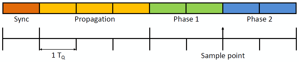
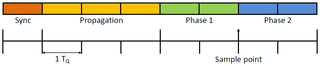
Time quanta (TQ for friends) is smallest time unit in CAN bus and it controls duration of a single bit. To represent a single bit, you need between 8 and 25 TQ. Those TQ units are further subdivided into synchronization segment (always 1 TQ), propagation segment (1-8 TQ), phase segment 1 (1-8 TQ) and phase segment 2 (1-8 TQ). Bigger the TQ, more control you have over fine bit tuning but at the cost of higher frequency need (i.e., 16 TQ subdivision will need double the frequency compared to 8 TQ to maintain same bit rate).

Synchronization segment always last for single quanta and CAN bus uses it internally to adjust bit edge. This ensures that various nodes don’t drift in time because of slight frequency differences. This is only segment with fixed duration.

Propagation segment that follows is there to compensate for a physical delay of the signal going over wire and its receival in driver. Rule of the thumb is that its value gets bigger with physical distance.

Phase segment 1 tells us duration (in TQ) before bit is actually sampled from line. Higher value you have, later sampling will occur. Actual sampling happens after sync + propagation + phase 1 quanta. More often than not, you want this time to be as close to the full quanta as possible.

Phase segment 2 is last segment and its duration concludes full bit time. It is very useful to keep this at at least 2 TQ because otherwise your sample point might get too close to edge of next bit.

First programming parameter that PIC will actually use is the baud rate prescaler (BRP). Based on it we determine bit rate according to following formula BRP = FREQUENCY / (2 * TQ * BITRATE). This value than gives you actual TQ time (TQTIME = 2 * (BRP + 1) / FREQUENCY). From that you can get duration of a single bit (TBITTIME = TQ * TQTIME). Since BRP value can only be integer, to get nominal bit rate PIC we use another calculation BITRATE = 1 / TBITTIME. If everything goes alright actual bit rate will match desired bit rate. If such thing does not happen, a bit of input parameter tweaking might be beneficial.

I prefer to calculate phase 1 duration next. General rule is to have it last as long as possible. Half of total bit duration is as good approximation as any. Of course, maximum of 8 TQ.

Propagation segment length gets calculated based on desired physical bus. I use standard 5 ns/m figure for bus delay and I add 250 ns as worst case processing delay in transceiver and use that as a minimum value. If TQ is higher propagation delay must be increased regardless of actual physical distance because of phase 1 and phase 2 having maximum of 8 TQ.

Phase 2 gets calculated from whatever is left after sync, propagation and phase 1 segment get their share.

Synchronization jump width is fuzziest of them all. In theory it would help you if clock drifts between nodes. However, make it too big and PIC starts detecting sync bits where there are none. I usually go with half of propagation length as a starting point and then I adjust it not to be longer than either phase 1 or phase 2. This gives a bit of wiggling space for clocks to drift but it is not overly aggressive.

Below is a small form which actually does these calculations. Might come in handy.

MHz
kbps
m
 
kbps
m
%
 
(- TQ)
(- TQ)
(- TQ)
(- TQ)

PS: Some additional information that might be useful:

Forcing Rebuild in MPLAB X.

Illustration

For a project of mine I needed a random serial number. I got it in Intel hex file not by memory address as you would commonly have, but by search & replace of a string. While I prefer this approach in most cases, it also meant that once code has been replaced, next replace would fail. I needed a rebuild.

Unfortunately MPLAB is too smart and it avoids rebuilding if no file has been changed. Of course there is no option to force rebuild either. Only thing left is to actually change a file or at least its time.

Under Linux there is a touch command. Under Windows there is an almighty copy. To update file time we need to simply execute:

COPY /B **source**+,,

To use this in MPLAB X go to project Properties, Building and check Execute this line before build. In text box underneath just apply newly found command on project’s main file (App.c in my case):

COPY /B **${ProjectDir}\App.c**+,,

Serial Number in Intel Hex

While doing an electronic project in MPLAB, I found it necessary to create an unique serial number for each device I program in order to have a proper USB functionality. Something as simple and often needed as this has to be already solved. Or so I thought.

Oh, I found solutions and solutions for this particular issue. Most of them were only useful with their device programmers - and I wanted something to work inside of MPLAB. Some other worked by modifying source code - a big no-no when you do source control. Some required serial number placed at an exact location - annoying (and volatile) to calculate in my case because USB serial number is a part of a bigger structure. Commercial solutions were also out of question… With each visited link I grew more firm in decision to roll out my own (“me hammer, problem nail” approach).

However, simple replacement is not necessarily an easy thing to do. You see, in world of microcontrollers Intel Hex format is the ruler. Without getting into details, format has two characteristics that make it suitable for firmwares. It splits data into fixed length blocks which is really nice when you have to do chip programming in blocks. Additionally every row is checksumed so data corruption can be avoided. Both those characteristics conspire against us to do simple file change. Not only that we cannot just simply change data because of checksum but we often cannot even simply find it because it can span across the rows.

So, it was a scripting time. Because of annoyingly difficult parsing, simple CMD was out of question. Only other choices were PowerShell or a completely custom program. While custom program would probably offer easiest development, I didn’t want to embed only executable. And embedding sources would mean that I would need Visual Studio on each machine I want to compile this at - to high cost in practicality. Only other choice really was PowerShell - environment that exists on every Windows 7 and higher machine.

Requirements were straightforward. I wanted something that would be a single call (Microchip’s MPLAB can call only single external build command). It had to replace file in-place (so that I could continue using PICkit 3 programming procedure). It had to change file as little as possible (e.g. by not removing extra headers). It had to support ASCII random (USB MSD specifications). And, lastly, it had to be capable of producing a valid output hex without checksum shenanigans.

I won’t dwelve into boring details and explain each part of code but it suffices to say that it loads whole file in memory, searches for placeholder and then replaces that placeholder with random value, adjusting the checksum as it goes. End result is the file that gets pushed onto the device.

Here is an example command (Project Properties, Conf, Building, Execute this line after build):

PowerShell.exe -ExecutionPolicy RemoteSigned -File ${ProjectDir}\..\Setup\HexReplace.ps1 **${ProjectDir}\dist\default\production\Source.production.hex** **197901281815** -**AsciiHexRandom** -Destination2 **${ProjectDir}\..\Binaries\TmpUsb.hex**

First part we might as well ignore because it is only preparing terrain for script by calling PowerShell. First meaningful argument is a location of an intermediate Intel hex file followed by a placeholder value. Since my device is USB based, I opted to have a valid serial number (197901281815) as a placeholder - makes live easier if script fails. Most common approach is to use something that won’t appear by accident (various number of X characters seem to be popular choice). Anything unique will do.

Switch AsciiHexRandom ensures that our randomness will be limited to numbers 0 to 9 and letters A to F, as required by MSD Bulk Only Transport 1.0 specification. If that parameter gets omitted random binary (0 to 255) will be used. Which one is better actually depends on your use case.

Last pièce de résistance is -Destination2 argument. That ensures script will not only change file but additionally copy it to a different place. It is not strictly necessary but I find it useful for archiving purposes. You can omit it without any consequence.

And that is my way of generating random serial number from within MPLAB project. Try it out and see whether it fits your needs.


PS: Script itself was not designed but grown. As such it is full of unoptimized code (just check function that does replacement) and it treats memory as kids treat candy. But realistically we are speaking about file that won’t be bigger than couple hundreds KB in the worse case scenario. I could not justify spending time I would need to make it “proper” when it already runs (unoptimized) within a fraction of a second.

PPS: Yes, I have cheated by embedding C# code inside of PowerShell.

PPPS: If something goes wrong, add -debug argument. That will give you a bit more information to go with.

OSH Park Just Got Bigger

Illustration

Last few years it got really easy to have your PCB manufactured in small quantities. All manufacturers shared similar price but each had its own peculiarities.

I find it very sad that one such manufacturer, BatchPCB, is closing its doors. It is not that I used them often. It is not that they were anything special. It is not even that they were cheap(er). It is just that I liked the choice.

Good news is that they were taken over by OSH Park. BatchPCB users can expect lower prices on smaller than 20 cm2 boards, they can expect ENIG finish (aka “gold”), and they can expect free shipping within USA.

Dream purple.

More Ohms Please

One of first things that you might learn as electronic hobbyist is that you should have 20 mA running through your indicator LEDs. For example, if you have 5 V power supply and your LED has voltage drop of 2V at 20 mA just give it 150 ohm resistor and you are golden.

And that is wrong. This recipe was valid 20 years ago but it is not something you should follow these days. If you have 20 mA coursing through LED, that is BRIGHT as hell. When you work in dark, every look at such device blinds you for minutes.

Don’t misunderstand me, I like to see some indication that device is alive but 1 mA or less should do the trick. These new LEDs are extremely efficient with their output and, while they still specify their current at 20 mA (or even higher), they will be bright enough at lower currents also.

PS: This rant is only about indicator LEDs; if your device needs to light-up the room, so be it.

Curious UART on 16F1516

Lately I have started using PIC16F1516 as my jelly bean PIC. It is cheap, has lot of memory (whooping 512 bytes) and it is fairly well feature-equipped. Best of all, it is almost completely compatible with my old favorite PIC16F1936.

Yes, PIC16F1936 has EEPROM built-in and both feature list and speed are superior. However, not all projects need all features and speed nor is lack of EEPROM something catastrophic.

As always I started programming by copy/pasting old code. Small adjustments were all that was needed. I copy pasted my UART routines and created simple echoing program on chip. And chip stayed quiet.

After some debugging it was obvious that both my timing routines and UART formulas are correct. And code was same as what I used on PIC16F1936:

void uart_init(int desiredBaudRate) {
    TRISC7 = 1; //RX
    TRISC6 = 0; //TX
    SPBRG  = (unsigned char)(_XTAL_FREQ / desiredBaudRate / 16 - 1);
    BRG16  = 0;    //8-bit
    BRGH   = 1;    //high speed
    SYNC   = 0;    //asynchronous mode
    SPEN   = 1;    //serial port enabled
    TXEN   = 1;
    CREN   = 1;
    asm("CLRWDT");
}

In moment of desperation I turned my attention to datasheet. And there, under Asynchronous Transmission Set-up chapter it said “Set the RXx/DTx and TXx/CKx TRIS controls to ‘1’.”

In all other PICs (I had opportunity to play with) TRIS for TX pin either does not matter or you set it to output. For some reason designers of this PIC decided that TX pin needs to be input in order for USART to work. Quite a trap.

Only change that was required was setting TRISC6 to 1 and my board became alive:

void uart_init(int desiredBaudRate) {
    TRISC7 = 1; //RX
    TRISC6 = 1; //TX
    SPBRG  = (unsigned char)(_XTAL_FREQ / desiredBaudRate / 16 - 1);
    BRG16  = 0;    //8-bit
    BRGH   = 1;    //high speed
    SYNC   = 0;    //asynchronous mode
    SPEN   = 1;    //serial port enabled
    TXEN   = 1;
    CREN   = 1;
    asm("CLRWDT");
}

PS: Do not forget to set ANSELC = 0.

How to Store Settings Without EEPROM

Having customizable setting in your PIC program is easy. Just define it as a constant and let XC8 handle everything else. If you need to change it during runtime there is bunch of code out there dealing with EEPROM access. But what if you want to store something in PIC without EEPROM?

In my case I needed to store two settings: Counter and Unit. Hardware device was already built around PIC without EEPROM so there was no choice but to use self-programming feature that almost all newer PICs share.

Idea is simple. Reserve some space in program memory by making some data constant (e.g. const char mySetting = 3;). Every time you access this variable PIC will return what it had stored there at time of programming. Our trick is to change those values by reprogramming code as it runs.

First complication comes from fact that you cannot just write in flash willy-nilly. Before each write you need to erase whole block of (usually) 64 bytes. Unless you are willing to write very complicated code that also means that you will always need to occupy whole block regardless of how many bytes you want to actually store.

Second caveat is that you can only erase whole block. That means that you cannot let compiler decide upon location of your data. You must select fixed location and that might give you :0: warning: segment "__SETTINGS_PROGRAM_text" (200-23F) overlaps segment "intcode" (8-273). Fortunately solution is really easy - just move your constant somewhere else. Of course that implies that you have enough free flash memory laying around.

Third issue might be that this operation typically takes few milliseconds which is ages in microcontroller terms. To make things worse interrupts must be disabled during almost all that time. Any precise time keeping is out of question.

However, if you wiggle your way around all these obstacles, you get nice storage for times when you just cannot afford EEPROM for one reason or another.

Full source follows:

#define _SETTINGS_FLASH_RAW { 0, 0, 0, 0, 0, 0, 0, 0, 0, 0, 0, 0, 0, 0, 0, 0, 0, 0, 0, 0, 0, 0, 0, 0, 0, 0, 0, 0, 0, 0, 0, 0, 0, 0, 0, 0, 0, 0, 0, 0, 0, 0, 0, 0, 0, 0, 0, 0, 0, 0, 0, 0, 0, 0, 0, 0, 0, 0, 0, 0, 0, 0, 0, 0 } //reserving space because erase block is block 32-word (64-bytes)
#define _SETTINGS_FLASH_LOCATION 0x0400

#define _SETTINGS_STORE_EMPTY { 0, 0 }
#define _SETTINGS_STORE_BYTES 2

#define _SETTINGS_REENABLE_GIE_AFTER_WRITE     1

const unsigned char _SETTINGS_PROGRAM[] @ _SETTINGS_FLASH_LOCATION = _SETTINGS_FLASH_RAW;

void _settings_write(int index, unsigned char data) {
    unsigned char newProgram[] = _SETTINGS_STORE_EMPTY;
    for (int i=0; i<_SETTINGS_STORE_BYTES; i++) {
        newProgram[i] = _SETTINGS_PROGRAM[i];
    }
    newProgram[index] = data;

    GIE = 0;

    EEPGD = 1; //point to Flash program memory
    CFGS = 0; //access Flash program memory
    WREN = 1; //enable write to memory

    TBLPTR = _SETTINGS_FLASH_LOCATION;
    FREE = 1; //enable block Erase operation
    #asm //erase block
        MOVLW 55h
        MOVWF EECON2 ; write 55h
        MOVLW 0AAh
        MOVWF EECON2 ; write 0AAh
    #endasm
    WR = 1; //start erase (CPU stall)

    TBLPTR = _SETTINGS_FLASH_LOCATION;
    for (int i=0; i<_SETTINGS_STORE_BYTES; i++) {
        TABLAT = newProgram[i];
        asm("TBLWT*+");
        #asm
            MOVLW 55h
            MOVWF EECON2 ; write 55h
            MOVLW 0AAh
            MOVWF EECON2 ; write 0AAh
        #endasm
        WR = 1; //start program (CPU stall)
    }
    WREN = 0; //disable write to memory

    if (_SETTINGS_REENABLE_GIE_AFTER_WRITE) { GIE = 1; }
}


#define _SETTINGS_INDEX_COUNTER  0

char  settings_getCounter() {
    return _SETTINGS_PROGRAM[_SETTINGS_INDEX_COUNTER];
}

void settings_setCounter(char data) {
    _settings_write(_SETTINGS_INDEX_COUNTER, data);
}


#define _SETTINGS_INDEX_UNIT 1

char  settings_getUnit() {
    return _SETTINGS_PROGRAM[_SETTINGS_INDEX_UNIT] % 3;
}

void settings_setUnit(char data) {
    _settings_write(_SETTINGS_INDEX_UNIT, data);
}

It would be best if you would keep this code in separate file (e.g. settings.h) and just include it from your main program file instead of pasting all this directly.

PS: If your program does not use interrupts change _SETTINGS_REENABLE_GIE_AFTER_WRITE to 0.

PPS: Do notice that flash memory was not intended as this kind of storage medium. Writing is much slower than EEPROM (because of erase) and endurance is much lower. Use it only in dire straits and be gentle.

PPS: This code is for PIC18F* series of micro-controllers. Same general principle works on PIC16F* but names of some registers might differ and additional NOPs might be required. Do check instruction manual.