Bad things happen when programmer finds a soldering iron

Framework Expansion Board

Illustration

One of most exciting recent developments in laptop world for me is definitely the framework laptop. A major component of that concept are its expansion cards. And, of course, you can build your own.

This repository is quite encompassing if you’re using KiCAD. However, for those who love nicer tools (ehm, DipTrace), it’s annoying to find that there is no board size specification in human readable format (and no, KiCAD XML is not). So I decided to figure it out.

To cut the long story short, here are the board outline points for the expansion card PCB:

  • (0.0, 0.0)
  • (26.0, 0.0)
  • (26.0, 26.5)
  • (25.0, 26.5)
  • (25.0, 30.0)
  • (17.7, 30.0)
  • (17.7, 28.0)
  • (16.0, 28.0)
  • (16.0, 29.0)
  • (10.0, 29.0)
  • (10.0, 28.0)
  • (8.3, 28.0)
  • (8.3, 30.0)
  • (1.0, 30.0)
  • (1.0, 26.5)
  • (0.0, 26.5)

In order to make it slightly nicer to handle, each corner is additionally rounded with a 0.3 mm radius.

And let’s not forget two holes at (1.7, 10.5) and (24.3, 10.5), both with a 2.2 mm diameter and 4.9 mm keepout region.

With that information in hand, one can create PCB board in any program they might prefer. Of course, I already did so for DipTrace and you download the files here.

And yes, PCB is just a first step in a development process. What I found the hardest is actually getting appropriate connectors for the enclosure as there’s not too much height to work with.


PS: No, I do not own framework laptop at this time. I am waiting for 15.6" model as 13.5" is simply too small for me when not used external monitor.

Battery Pack Load

Illustration

Powering device via USB has its advantages even if device doesn’t need connectivity. Most notable of those advantages is a wide availability of USB battery packs. That makes powering device really easy. However, what if your device uses so little power that batter pack keeps turning off?

All three battery packs I had available had the same issue. Put something that pulls just a trickle of current and they would turn off. One of them did have a trickle-charge functionality and that sorta worked but required manual intervention. And yes, I forgot to turn it on more times than I care to remember.

So I went looking for solution and found Dorkbot PDX article by Paul. The way how he solved this issue was quite a nice one. Just put intermediate load on the bus and you’re golden. Instead of going with his solution, I decided to use my favorite hammer - Microchip PIC microcontroller - to make my own board using the same concept.

Realistically, there’s no reason to use microcontroller for this. Having a programmable part just introduces assembly complexity and you cannot use it out of box, without programming it first. But there are advantages too. The major one being adjustability and that came in really handy when figuring out the timings needed. Instead of dealing with large value capacitances, one can use inherit time keeping mechanisms of microcontrollers. Furthermore, it also allowed for easy placing of blinky light. And who doesn’t love those?

The whole solution is based on a small 6-pin PIC10F200 microcontroller. When you discount programming pins, that leaves you one pin to work with. And yes, you can pretty much use programming pins too (3 of them) if you use a few extra passives but I generally leave them alone if I can. Fortunately, application I had in mind was simple enough to solve with a single pin.

Illustration

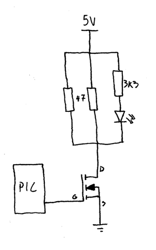
The device logic is as simple as it gets. To keep the battery pack turned on, it uses MOSFET to pull 200 mA over two resistors for about 20 milliseconds. Once pulse is sent, wait for 10 seconds. Rinse-repeat. On all packs I’ve tried this combination worked flawlessly. Of course, if there’s a pack where this doesn’t work, adjustment is easy enough (yes, I will update code with some constants later :)).

The heavy lifting is done by MOSFET driven directly by microcontroller. Once turned on, it will allow two resistors to dissipate a bit over 200 mA of current. While this seems like a significant amount of power to pass over puny 0805 resistors, short duration means they will never get hot enough to present a problem.

One could also take an offense to how MOSFET is driven too. Due to the nature of the beast a lot of current will flow out of the gate pin and by common knowledge one has to have a resistor to limit it. However, this MOSFET is small enough that current limiters built-in to Microchip PIC microcontrollers are fine. I had even bigger MOSFETs work in circuit for years without gate resistor so I am not too worried. That said, if I ever change to different microcontroller, some reevaluation will be needed.

And yes, there is no bleed-off resistor on MOSFET gate either. If circuit is powered on, PIC will be driving it either low or high so pulling the MOSFET gate down is not really needed. If circuit is not powered on, who cares - there’s no power to go around anyhow. That leaves only the short amount of time when circuit is powered on and PIC is not yet driving the gate. And that is the interval we can safely ignore as it’s shorter than 20 milliseconds and even erroneously active MOSFET will cause no damage to the circuit in that time.

Thanks to Microchip’s semi-standard pinout, this device can use any number of PIC microcontrollers. As long as footprint fits (SOT23-6), you’re golden. I have tried it with already mentioned PIC10F200 and PIC10F320 but any variant should work too. Yes, the firmware did need a bit of adjusting between methuselah PIC10F200 and newish PIC10F320 but those were simple enough. In these times of chip shortages, having multiple parts fit is always a nice thing.

Illustration

How much battery this uses, you might ask. It would be a bit annoying to have your battery drained by a device whose only purpose is to keep it awake. Well, to start with, we need to account for all power usage. The main one is of course our 220 mA pulse (5V/(47Ω÷2)) lasting 20 milliseconds. Since it repeats every 10 seconds, that leads us to a duty cycle of 0.2%. Multiply one by another and we can see that average power usage is about 0.5 mA.

Second power user is our LED that blinks with the pulse. Due to large value resistor, it will require slightly less than 1 mA for each pulse. Using our duty cycle, that us average consumption of 2 µA (0.002 mA). Pretty much a noise compared with our load.

And lastly there’s the PIC itself. Good news is that this is well under 1 mA. How much under? I have no idea as I didn’t have anything capable of measuring it. I will definitely need to create a board for that too. However, I did use USB power meter to get a long term reading of the usage and it was slightly under 0.5 mA (averaged over an hour) if using PIC10F320. For older PIC10F200 usage is a smidgen above it.

Those reading more carefully might wonder, if a power pulse needs about 0.5 mA, and total consumption is under 0.5 mA, we have the free energy as microcontroller is actually using the negative power from a far dimension to run itself. Sadly, it’s not so. Due to how MOSFET is driven, it won’t turn on nor it will turn off instantly. So our 200 mA pulse average will actually be lower. And PIC consumption is low enough to “hide” in those numbers.

Code actually runs constantly in the background due to a quirk of PIC10F200. If you put it in sleep, it resets itself (by design) making it annoying to keep track of time longer than 2.3 seconds. I was toying with idea of just using the newer PIC10F320 but power usage of constantly running PIC was low enough that I decided not to care.

Either way, if you have 10000 mAh battery, this device could theoretically run for 20000 hours. Suffice it to say that it shouldn’t reduce battery life too much. If you really want to squeeze the last possible mAh out of it, you could adjust timings. For example, my Anker power bank was quite happy with more than a minute between pulses (0.033% duty cycle). However the default 0.2% duty cycle is probably a good starting point when it comes to compatibility.

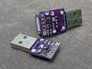
Lastly, there are actually two versions of the device. The “normal” one just plugs in USB port while pass-through has a female USB connector on it allowing it to be used on battery packs with a single type A output. You can find gerbers for both on GitHub alongside with the source files.

Dealing with part shortage - Microchip edition

Illustration

For a small electronics project of mine, I needed literally only one output pin. My go-to part for these situations is PIC10F200. It’s a 6-pin SOT-23 device offering internal oscillator and not much more. Microcontrollers don’t really get smaller/simpler than this.

Due to the hamster habits I have, I actually had enough enough parts to finish up the prototype so the only thing left was to order a few more parts of DigiKey. Well, as many components lately, my favorite PIC was out of stock.

However, when one door closes, another one opens. Microchip is really good at keeping pinout similar over multiple microcontrollers. And DigiKey had PIC10F202, PIC10F206, PIC10F220, PIC10F222, and PIC10LF322 available in stock. While all these PICs are slightly different, they share the same basic pinout. And for my project any of them would do. Even if I used some less common feature, Microchip often has multiple products differing only in memory amount.

While hardware might be similar enough, firmware does have significant differences - especially between older PIC10F206 and newer PIC10LF322 setup. Even turning LED on/off uses different registers between them. Instead of having different firmware for each, one can make use of compiler directives and check which PIC is actually being used. Something like this:

#if defined(_10F200) || defined(_10F202) || defined(_10F204) || defined(_10F206)
    GP2 = 0;                // turn off GP2
    TRISGPIO = 0b11111011;  // GP2 is output
#else
    LATAbits.LATA2 = 0;    // turn off RA2
    TRISAbits.TRISA2 = 0;  // RA2 is output
#endif

While out-of-stock syndrome has hit Microchip too, with a bit of care, they do make transition feasible if not always trivial.

Adding USB to A-BFastiron SS-305MP

Illustration

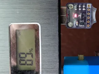
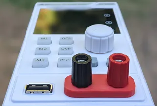
I needed a cheap power supply for a project and it was easy to find a nice one in A-BFastiron SS-305MP. It was small enough, looked good, and had shiny display. What could man want more?

Well, when I got it and saw cutout for USB, I know what more I wanted. An USB port.

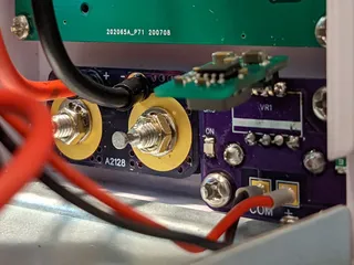
And strangely enough once you open the power supply, you’ll find connector providing about 8.2 V already there without anything to plug into. It’s almost as if somebody placed it there to be an input for 5V linear voltage converter and then later figured electronics and heatsinking would cost too much and covered the hole. And yes, it’s a proper hole cover that you can remove - no drilling necessary.

If you open power supply you will even find standoffs already in place. It’s simply begging to have PCB mounted in.

First thing to figure out was which USB connector will fit. Searching on DigiKey found quite a few of them roughly matching the dimensions. So I just selected the cheapest one that matched standard footprint. And yes, looking on side you might find it protruding a bit too much but not criminally so. It might be original designers were fine with this or the had a custom length connector in mind. For me this was as good as it gets.

With connector found, it was time to figure PCB. And I decided to keep it really simple. The whole setup would revolve around VXO7805-1000. It’s a nice DC-DC switching regulator that will take any input higher than 8 V and drop it down to 5 V with some efficiency. In its pinout it emulates beloved LM7805 but at 90% efficiency and without all the heat.

Regulator itself requires just two capacitors and I decided to go just with them. I was tempted to add a smaller 1 µF capacitor to output and maybe even a 100 nF one for decoupling purposes but decided against it. Due to wide variety of cables and outputs USB device might face, all of them already have more than sufficient decoupling and adding more wouldn’t really do anything. So why waste a component.

The only really unneeded components would be an LED and its accompanying resistor. While they serve no function, I really love to have an indicator of output. If there was ever an issue, looking at LED would at least tell me if power is going out. And quite often that’s quite a big help.

Speaking of power going out, I don’t consider a fuse optional. It’s a minimum you need in this setup. Another thing I would consider bare minimum for power supply would be a short-circuit detection but that’s fortunately already a part of voltage regulator. And yes, I could have gone further, especially by adding reverse polarity protection to the input and I was tempted but in reality you’ll just connect this thing once and leave it connected. As long as you connect it correctly the first time, you’re good.

Illustration

Connecting all this to the power is entrusted to any JST-XH 2-pin cable - 10 cm in length. Just make sure that the negative wire is going next to COM marking on the power supply motherboard. If in doubt, just double-check with voltmeter.

And that’s it. For a few bucks more and some extra soldering, we have a nice 500 mA USB port at the front of the power supply. Just in case we need it.

On GitHub you’ll find source files and releases with gerbers and part list.

Changing A-BFastiron SS-305MP Binding Posts

Illustration

I needed a cheap power supply for a project and it was easy to find a nice one in A-BFastiron SS-305MP. It was small enough, looked good, and had shiny display. What could man want more?

Well, how about proper binding posts?

And no, I am not only talking about quality albeit one coming with it are quite flimsy and it already arrived with one cracked. I am talking about spacing. I simply hate when binding posts don’t observe standard ¾" distance between them.

And this power supply almost had it right. I measured spacing to be a smidgen over 20 mm while standard would call for 19.05 mm. With such a small difference, there was literally no reason to go non-standard. But non-standard they went.

If you open the power supply, you’ll see that binding posts are held by the PCB in the back. Thick wires are soldered onto it and nuts are used to connect to posts themselves. So the whole operation can be done with a simple PCB update with correct spacing. Only thing needed extra is a bit of filing action and you can reassemble it all.

However, since my binding post was already cracked, I decided to swap them for Pomona 3760 (black and red) set. But that brought another issue - panel cutout for them is completely different. And yes, a patient man might shape it enough, but for those with 3D printer there’s an easier solution.

Illustration

To mount it all, I used some nice red MH Build PLA to print really tight mounting base and spacer for posts.

After filing plastic a bit to expand holes toward each other, I placed binding posts into the printed base, pushed it through the hole, used another 3D printed spacer on inside and added some more height to set using spacers that came with binding posts themselves. Then in goes the custom PCB and finally all can be fastened using lock washer and nut that cane with posts.

Result are nice binding posts at proper spacing. :)

On GitHub you’ll find source files and releases with gerbers and part list. 3D model can be found on TinkerCAD.


PS: The only downside of Pomona is that it uses ¼" imperial nuts while the power supply originally had 7 mm nuts. So, in addition to metric socket set you already have, you’ll need a witchcraft-sized set too.

Well Grounded

Playing with electronics as a hobby has its advantages. Most notably, I don’t need to deal with high-speed signals or EMC most of the time. However, in the days of faster and faster I/O, high-frequency content “sneaks in” whether you want it or not. Just because your microcontroller works at 48 MHz, that doesn’t mean your I/O edge is not (much) faster. And sorting out those issues is hard.

Fortunately, there are many “rule-of-the-thumb” guides out there, but I found none better than Rick Hartley’s. Well worth the watch.

DKRed

Illustration

While I use OSH Park most of the time, I always like to look at different services, especially if they’re US-based. So, of course I took a note of DigiKey’s DKRed. Unfortunately, review will be really short as I didn’t end up using it.

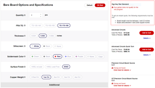
On surface it looks good. Board requirements are reasonable. If you want to use DKRed service you need to have your design fit 5/5 mil minimum - more than sufficient for all I do. While more detailed specifications are available for other PCB vendors on their platform (albeit Royal Circuits has a bad link), there’s nothing about DKRed itself. Yes, I know DKRed might use any of manufacturer’s behind the scene but I would think collating minimum requirements acros all of them should be done by DigiKey and not left to a customer.

And not all limitations are even listed on that page - for example, fact that internal cutouts are not supported is visible only in FAQ and whether slots are supported is left as a complete secret. Compare this to OSH Park’s specification and you’ll see what I mean.

But ok, I went to upload one small board just to test it. And I was greeted by error that length is shorter than 1 inch. As I love making mini boards smaller than 1", I guess I’m out of luck. But specification page did correctly state that fact so I cannot be (too) angry. Never mind - I’ll try a slightly bigger board. Nope - it has to be more than 4 square inches in area. Something that I didn’t find listed anywhere.

Well, I had need for one board 65x72 mm in size - that one would work. And yes, DKRed finds that board OK. But cost is $43.52. OSH Park charges $36.25 for the same board. And yes, DKRed gives 4 boards ($10.88 per board) while OSH Park only provides 3 ($12.08 per board) so it’s slightly cheaper if you really need all 4 boards. If you’re hobbyist requiring only 1 board like me, you’re gonna pay more.

And this is where I stopped my attempts. Breaking deal for me was the minimum size as this makes it a no-go for most of my boards. And cost for just a prototyping is just too high. Mind you, it might be a good deal for people regularly working with bigger boards at a small quantity. But it’s not for me.

Randomness in 8-bit Microchip PIC

Generating pseudo-random (or even fully random) numbers on desktop computers is mostly a solved problem. However, what if we need to generate random numbers on much smaller devices? For example, on Microchip’s 8-bit PIC16F1454 microcontroller?

Good news first, mersenne twister is no longer the only player in town. These days we have a whole family of both faster and more random algorithms courtesy of Guy Steele and Sebastiano Vigna. Their xoshiro / xoroshiro generators cover essentially any combination of speed and memory needs. They are probably a pinnacle of randomness quality you can fit in such a minimal space.

Since I did need a minimal footprint, I first selected xoroshiro64**.

uint32_t rotl(const uint32_t x, int k) {
    return (x << k) | (x >> (32 - k));
}

uint32_t s[2];

uint32_t next(void) {
    uint32_t s0 = s[0];
    uint32_t s1 = s[1];
    uint32_t result = rotl(s0 * 0x9E3779BB, 5) * 5;

    s1 ^= s0;
    s[0] = rotl(s0, 26) ^ s1 ^ (s1 << 9);
    s[1] = rotl(s1, 13);

    return result;
}

This code will generate random numbers that pass vast majority of DieHarder randomness tests and all that just in 58 bytes of data memory and 365 words of program memory (freeware XC8 2.31, with optimizations).

While this is probably as small as a good random number generator can reasonably get on a microcontroller, Microchip PIC is an 8-bit device at heart and dealing with 32-bit values doesn’t come naturally. Fortunately, xoroshiro algorithm family scales reasonably well and one can “borrow” the setup.

Here is my stab at making xoroshiro a bit more 8-bit friendly.

uint8_t rotl(const uint8_t x, int k) {
    return (x << k) | (x >> (8 - k));
}

uint8_t s[2] = { 0, 0xA3 };

uint8_t next(void) {
    uint8_t s0 = s[0];
    uint8_t s1 = s[1];
    uint8_t result = s0 + s1;

    s1 ^= s0;
    s[0] = rotl(s0, 6) ^ s1 ^ (s1 << 1);
    s[1] = rotl(s1, 3);

    return result;
}

Now, this is a simplified version and definitely not as random as the full implementation. Obvious change is in a state variable size (16 instead of 64) and calculation is taken from xoroshiro128+ so that multiplication can be avoided. There are no multiplication circuits in 8-bit PIC microcontrollers and thus this makes code much smaller and faster.

Lastly, the half of initial state is fixed to 0xA3. When dealing with such a small state, not all combinations of initial state are valid nor they produce equally long period and this is essentially just a workaround to keep numbers coming.

This simplified version needs 10 bytes of data memory and takes only 65 words of program memory. A great improvement (more than 5x in both data and program memory) albeit at significant randomness cost. First of all, you essentially only get 256 seeds with large enough period (64897 bytes). Secondly, the whole space can be only 16-bits to start with. While this might barely pass a few DieHarder tests (e.g. birthdays, 2dsphere, dab_dct, and rgb_permutations), it won’t come even close to the full xoroshiro64** in terms of randomness quality. And let’s not even mention higher state size algorithms.

That said, if you just need random numbers for a game or something similar on a highly constrained device, I would say that quality trade-off is worth the speed and memory usage improvements.


PS: If you initialize random number generator with static values (which is perfectly valid), you will always get the same set of random values. Sometime that is a desired feature (e.g. during debugging) but we usually want something more unpredictable. Assuming you’re using the chip with a separate low-frequency oscillator (LFINTOSC), you can rely on a drift between it and a high-frequency oscillator to get a reasonably random seed.

void init(void) {
    // setup timer if not already in use
    T1CONbits.TMR1CS = 0b11;
    T1CONbits.T1OSCEN = 1;
    T1CONbits.TMR1ON = 1;

    _delay(4096);  // just to improve randomness of timer - can be omitted

    // initialize using timer values (ideally you would wait a bit after starting timer)
    s[0] = TMR1L;
    s[1] = 0x2A;  // important to get high periods and to avoid starting from 0x0000
}

PPS: No, xoshiro algorithms are not cryptographically secure. If you need to generate keys on microcontrollers, look into specialized hardware. These algorithms are intended for general-purpose randomness.

PPPS: Code is available for download. It will use 10 bytes of data memory and should fit into 82 words of program memory with initialization from LFINTOSC.

Storing Settings on PIC16F1454

As I was playing with PIC16F1454, I came to the point where some configurability would be in order. You know how it goes with PIC microcontrollers - just write it in EEPROM and you’re good. Unless there is no EEPROM like there is none for PIC16F1454.

Never mind, I had this issue before, so I can just copy my own code (ab)using program memory for the same purpose. Guess what? There are some issue with this too.

The first of all my old code was for different microprocessor. While principle is the same, it’s not an exact match. The second reason was changes to XC8. My old code doesn’t properly compile on XC8 2.00 - they changed how location is defined. The third (and the last) reason is high-endurance flash that PIC16F1454 supports. Unlike normal flash that’s rated for 10K writes, last 128 of this PICs program memory is rated to 100K. Albeit 10K is nothing to frown about, 100K is much nicer - especially if I end up changing data a lot.

Second and third reason share the same fix. Memory definition looks like this:

#define _SETTINGS_FLASH_RAW { 0, 0, 0, 0, 0, 0, 0, 0, 0, 0, 0, 0, 0, 0, 0, 0,
                              0, 0, 0, 0, 0, 0, 0, 0, 0, 0, 0, 0, 0, 0, 0, 0 }
#define _SETTINGS_FLASH_LOCATION 0x1FE0

const uint8_t _SETTINGS_PROGRAM[] __at(_SETTINGS_FLASH_LOCATION) = _SETTINGS_FLASH_RAW;

This will use the last 32 bytes, starting at 0x1FE0. This address is conveniently 32 bytes before end, falling without issues within “the last 128 bytes” high-endurance category. Now, if you need more memory, just make the array bigger and move it more forward. Just remember to do so in 32-byte increments as this is the block size for flash erase operation. If you don’t reserve all that memory, you might end up erasing your code and we wouldn’t want that. I personally never had need for more than 32 bytes of memory (i.e. one flash page) but your use case might differ.

All settings can be held in structure. Here I will have two settings - Address and DisplayHeight:

typedef struct {
    uint8_t Address;
    uint8_t DisplayHeight;
} SettingsRecord;

SettingsRecord Settings;

To read these settings, we just need to copy our reserved data (seemingly in _SETTINGS_FLASH_RAW variable) into the structure:

uint8_t* settingsPtr = (uint8_t*)&Settings;
for (uint8_t i = 0; i &lt; sizeof(Settings); i++) {
    *settingsPtr = _SETTINGS_PROGRAM[i];
    settingsPtr++;
}

Writing is a two step process. It starts by erasing the WHOLE 32-word/byte block. Following that, we get to write each byte separately:

bool hadInterruptsEnabled = (INTCONbits.GIE != 0);
INTCONbits.GIE = 0;
PMCON1bits.WREN = 1;  // enable writes

uint16_t address = _SETTINGS_FLASH_LOCATION;
uint8_t* settingsPtr = (uint8_t*)&Settings;

// erase
PMADR = address;         // set location
PMCON1bits.CFGS = 0;     // program space
PMCON1bits.FREE = 1;     // erase
PMCON2 = 0x55;           // unlock flash
PMCON2 = 0xAA;           // unlock flash
PMCON1bits.WR = 1;       // begin erase
asm("NOP"); asm("NOP");  // forced

// write
for (uint8_t i = 1; i &lt;= sizeof(Settings); i++) {
    unsigned latched = (i == sizeof(Settings)) ? 0 : 1;
    PMADR = address;            // set location
    PMDATH = 0x3F;              // same as when erased
    PMDATL = *settingsPtr;      // load data
    PMCON1bits.CFGS = 0;        // program space
    PMCON1bits.LWLO = latched;  // load write latches
    PMCON2 = 0x55;              // unlock flash
    PMCON2 = 0xAA;              // unlock flash
    PMCON1bits.WR = 1;          // begin write
    asm("NOP"); asm("NOP");     // forced
    address++;                  // move write address
    settingsPtr++;              // move data pointer
}

PMCON1bits.WREN = 0;  // disable writes
if (hadInterruptsEnabled) { INTCONbits.GIE = 1; }

The first and last step is dealing with interrupts. During write interrupts must be disabled. Code will disable them before writing and re-enable them afterward if needed.

Erase is easy enough. Just set FREE bit in the PMCON1 register followed by magic incantation (0x55, 0xAA, WR=1) and wait for a millisecond or two. Do note that NOP instructions are mandatory due to how self-writing program memory works. It’s one of the rare instances where NOP actually serves a purpose in C code.

To write data, process is close enough. Load all the bytes you wish to write using PMADR and PMDAT registers to set address and data. All bytes except the last will have LWLO bit set and will just cause loading of data into latches. The last byte must have LWLO cleared, signaling we’re done with writing. After a millisecond or two, bytes are done.

Two things are slightly curious there. The first one is setting of PMDATH to 0x3F. This value is actually the same as for erased cell and this just means we’re not changing it’s value. Note that upper byte is not the part of high-endurance flash and only 6-bit value (words are 14-bits on this PIC). Thus we really shouldn’t use it. The second strange decision is to start loop from 1 instead of the more conventional 0. This is so that we can determine if we’re at the last byte without substracting one.

In any case, this is all you need to make your program memory work as a storage for your settings.


PS: Procedure is the same on PIC16F1454, PIC16F1455, PIC16F1459, and probably quite a few more.

PPS: Whole code is available in Git repository.

PPPS: There is quite useful application note from Microchip (AN1673A) dealing with high-endurance flash. Their code uses similar but slightly different approach. If you don’t like this code, maybe theirs will tickle your fancy.

Duplicating Non-Reentrant Functions

Illustration

As I was playing with PIC16454 using USB, I kept getting these warnings: Microchip/usb_device.c:277:: advisory: (1510) non-reentrant function "_USBDeviceInit" appears in multiple call graphs and has been duplicated by the compiler

This was due to function being called from both main function and from interrupt handler. Since function could be interrupted at any point in time, this was definitely a problem and compiler did find a valid solution. However, this was a bit suboptimal for my case.

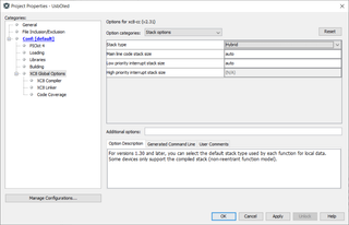
Since I had issue with only a few functions, I decided to make use of Hybrid option is XC8 compiler stack options. With this option warnings were gone. Surprisingly, this also made my code smaller. Hybrid stack compiled into 7181 words while standard Compiled stack was 7398.

If you have reentrancy happening in just a few functions, Hybrid option might be good for you.*


* Some restrictions apply. Please contact your fellow developers if your compile lasts longer than 4 hours.