Rendering KiCAD PCB to PNG
I have pretty much automated creation of KiCAD export files thanks to its command line interfacehttps://docs.kicad.org/8.0/en/cli/cli.html). However, there was always one thing missing - image for each PCB. Yes, not really necessary for manufacturing but it’s really handy when you want to just quickly check things without starting KiCAD and/or for any inventory system.
Before KiCAD 8, getting a PCB image required exporting to .step file and then converting stuff around. It got complicated enough with all the prerequisites that I have essentially given up. Fortunately, that’s not true anymore, and now we can get .wrl files that can be often used directly.
kicad-cli pcb export vrml --output "board.wrl" "board.kicad_pcb"While exported files don’t include lights, this usually doesn’t matter to viewers who add their own. However, for our processing, we want to add light that is just slightly to the top-left (at 0.1 -0.1 -1) of the camera (at 0 0 -1).
head -1 "board.wrl" > "board.front.wrl"
cat <<EOF >> "board.front.wrl"
Transform {
    children [
        DirectionalLight {
            on TRUE
            intensity 0.63
            ambientIntensity 0.21
            color 1.0 1.0 1.0
            direction 0.1 -0.1 -1
        }
EOF
cat "board.wrl" >> "board.front.wrl"
echo "] }" >> "board.front.wrl"
And yes, this method is a bit crude but it does work.
In order to reduce this 3D model into 2D image, ray tracing comes in handy. However, for that we need an external tool. I found that RayHunter worked great from the command line. While you only need that tool, you might want to check Castle Model Viewer as it can show you parameters in a bit more interactive way. Please note you also need libpng-dev package for PNG output.
cd ~/Downloads
wget https://master.dl.sourceforge.net/project/castle-engine/rayhunter/rayhunter-1.3.4-linux-x86_64.tar.gz
tar xzvf rayhunter-1.3.4-linux-x86_64.tar.gz
sudo install -m 0755 ~/Downloads/rayhunter/rayhunter /usr/local/bin/rayhunter

sudo apt install --yes libpng-dev
With prerequisites out of way, now we can finally export our board, looking directly at its front side. Camera position is a bit further away than I usually need it for my board but resolution of 4320x4320 pixels is large enough to then later crop the unneeded pixels.
rayhunter classic 7 \
    4320 4320 \
    "board.front.wrl" \
    "board.front.png" \
    --camera-pos 0 0 6 \
    --camera-dir 0 0 -1 \
    --scene-bg-color 1 1 1
You can see what each parameter does in rayhunter documentation
If all went fine, this will give you PCB board nicely rendered but with quite a lot of whitespace. In order to remove those extra pixels, I like to use ImageMagick.
sudo apt install -y imagemagickUsing convert command I trim all the whitespace, resize it to 1060x1060 pixels, add 10 pixels boarder on each side, and finally extend it to the full 1080x1080 size.
convert \
"board.front.png" \
-trim \
-resize 1060x1060 -normalize -density 600 \
-bordercolor white -border 10 \
-gravity center -extent 1080x1080 \
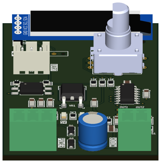
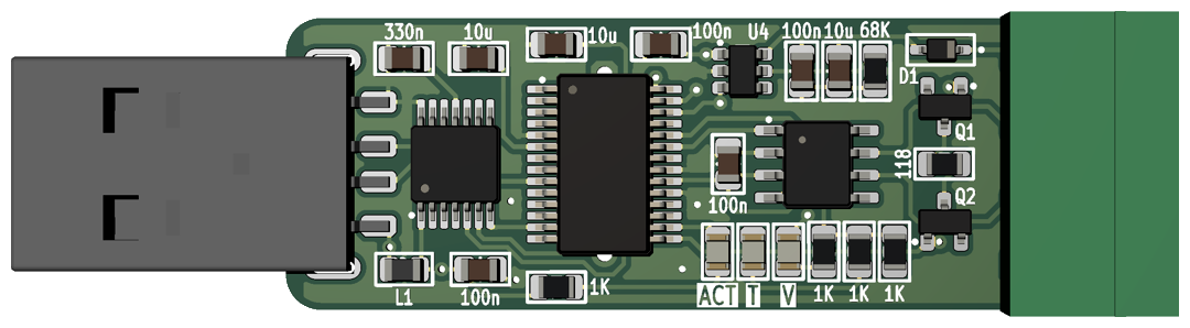
"board.front.png"Congrats, your PCB image should be looking good just about now.
PS: You can do this from any PCB orientation by just adjusting camera and light position.