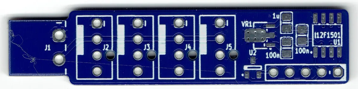
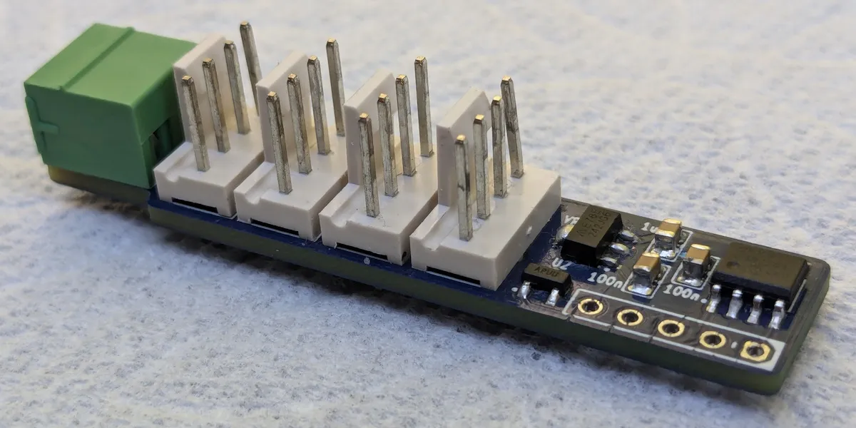
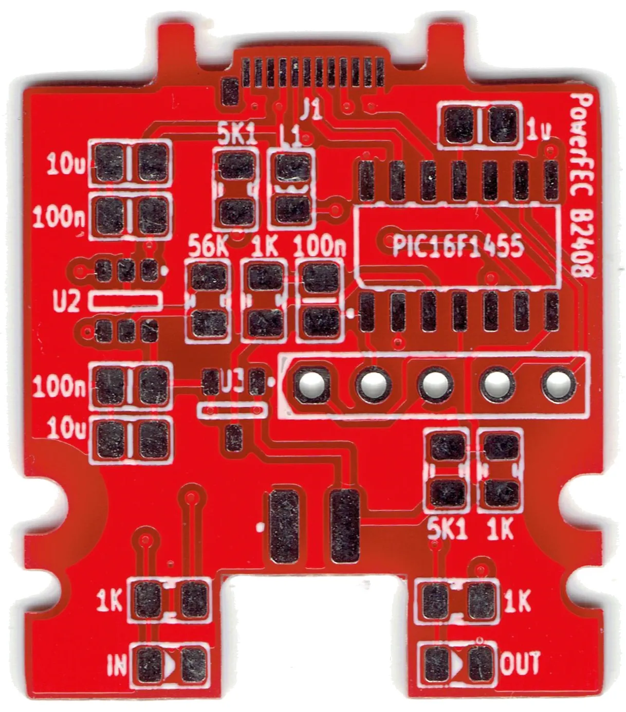
AuxPower1U: Switching the High Voltage
This is a post 9 in the series (next: Main Controller PCB, previous: Fan Controller).

Using a MOSFET as a switch is easy. Select any P-MOSFET, make sure it works at your board’s logic level, supports enough sweet amps, and you’re golden. I can almost guarantee that any MOSFET that satisfies those parameters will be good enough. Just pull it down to earth when you want lights to go out.
However, this doesn’t work for high-voltage DC circuits. Now, people can disagree on where the “high voltage” begins. When it comes to switching DC power, for me that limit is somewhere around 20V. This is the limit where you cannot use “normal” components without care, nor can you expect your circuits that worked just fine to continue operating. It’s the land of magic smoke.
For AuxPower1U, power supplies go up to 60V. And it’s not hard to find a MOSFET that goes that high. However, driving that MOSFET is another story. In order for it to be fully off, you cannot just use 5V - that’s not high enough to turn the MOSFET off if there’s 60V passing through it.
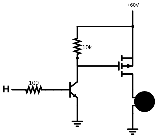
A simple solution is just pulling the gate up to your switched voltage - 60V will definitely turn it off. The only problem is that this also brings 60V at your microcontroller’s doorstep. But, with a bit of thought, you can see it’s not a catastrophic issue - an optocoupler or even a simple transistor will provide enough isolation to keep the microcontroller happy.
But more devious problem lurks underneath - often overlooked Vgs specification. Most of the time, you only get a 20V difference between gate and source to play with. In practice, to drive 60V, you can only go as low as 40V on the gate. Going all the way to ground is definitely out of question.
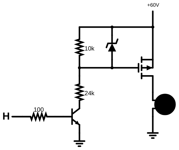
To resolve this, we can (ab)use the fact that a MOSFET has quite a high input impedance. Thus, a humble voltage divider will allow us to keep it at just below 20V of difference. In a 60V case, that means 10K/24K resistor values resulting in about 18V of voltage difference. If we want to be extra safe, placing a zener diode will further limit the maximum voltage. Ideally, you want the zener’s voltage rating to be slightly above the expected voltage (while still under 20V) in order to minimize power usage. In this case, an 18V zener will do nicely since the voltage divider sits just under that voltage.
Making this circuit usable for many different voltages involves a decision on the minimum voltage and setting up a voltage divider to the minimum viable Vgs value. We expect the zener to “clip” higher voltages so that’s the only calculation you need. Zener’s power rating is not really important in this case since the currents involved are low enough.
Of course, having a working switch is just the start of the story. Depending on your needs, you might need to fiddle with the circuit a bit. For example, increasing resistance lowers power usage but it might not work properly over the whole range (moslty dependant on the MOSFET input leakage). And let’s not even go into what happens if we want to do fast switching.
This is a generic, high-voltage MOSFET driving circuit intended for “slow” switching of DC voltage, and it’s a good starting point.
PS: Yes, I know that I am missing a minus (-) sign in front of many voltages since we are dealing with P-MOSTFETs. I decided to remove them for clarity.