World of networks

Mint Cacti for Mikrotik Queue

Illustration

Mikrotik does routing beautifully but the same cannot be always said about its traffic monitoring facilities. While graphing does exist, its is as flexible as Trump supporter on immigration issues.

For me, one of the best ways to monitor router on the cheap is Cacti. Completely free and has built in SNMP support. Guess what else has built in SNMP support? Yep - Mikrotik.

To get Mikrotik’s SNMP working, just enable it from terminal window, adjusting firewall if necessary:

/snmp set enabled=yes

/ip firewall filter
add chain=input protocol=udp dst-port=161 in-interface=!ether1 action=accept place-before=0 comment="Allow local SNMP"

While we are playing with Mikrotik, we can also print OIDs for queues:

/queue simple
 print oid without-paging
 0    name=.1.3.6.1.4.1.14988.1.1.2.1.1.2.19
      bytes-in=.1.3.6.1.4.1.14988.1.1.2.1.1.8.19
      bytes-out=.1.3.6.1.4.1.14988.1.1.2.1.1.9.19
      packets-in=.1.3.6.1.4.1.14988.1.1.2.1.1.10.19
      packets-out=.1.3.6.1.4.1.14988.1.1.2.1.1.11.19
      queues-in=.1.3.6.1.4.1.14988.1.1.2.1.1.12.19
      queues-out=.1.3.6.1.4.1.14988.1.1.2.1.1.13.19
 ...

Just store this data somewhere are we are going to need bytes-in and bytes-out entries later.

To get Cacti running, I went with the latest Linux Mint distribution. Procedure is quite generic so you can select essentially any Linux. Just add a few packages:

sudo apt-get -y install lamp-server^
sudo apt-get -y install snmpd
sudo apt-get -y install cacti cacti-spine

During installation, some packages might have additional questions - especially password related - you might want to set. For the purpose of this exercise I just went with all defaults.

After all packages are installed, it is a good time to test if we get anything from Mikrotik:

snmpwalk -v 2c -c public ^^192.168.88.1^^

And yes, this command is going to show a lot. :)

Now that we know SNMP is working we can go further with Cacti setup. For that we go to http://127.0.0.1/cacti and answer a few questions - essentially just setting the admin password and confirming tool locations.

The next thing on Cacti’s Console page is selecting Devices and adding a new one. You need to enter Mikrotik’s IP address here and change SNMP version to 2. Once you create entry, you should see system name and uptime.

Now we can finally go to New Graph and create one based on SNMP - Generic OID Template. For the purpose of byte counting Maximum Value should be set to U and OID should be one belonging to Mikrotik’s queue byte count. In my case value .1.3.6.1.4.1.14988.1.1.2.1.1.8.19 is the one used for input bytes of my Internet queue. A few minutes afterward you can check your Graphs/Preview tab and you should see your data nicely displayed.

Of course, with Cacti’s seemingly infinite configurability, this is just a start. Feel free to snoop around and discover. :)

PS: To monitor router’s health, check out resource OIDs:

/system resource print oid
             uptime: .1.3.6.1.2.1.1.3.0
    total-hdd-space: .1.3.6.1.2.1.25.2.3.1.5.1
     used-hdd-space: .1.3.6.1.2.1.25.2.3.1.6.1
       total-memory: .1.3.6.1.2.1.25.2.3.1.5.2
        used-memory: .1.3.6.1.2.1.25.2.3.1.6.2
           cpu-load: .1.3.6.1.2.1.25.3.3.1.2.1

OpenVPN or SSTP on Mikrotik?

As I have covered creating both OpenVPN and SSTP server on Mikrotik, one might rightfully wonder - which one is better?

Security-wise, on Mikrotik, they are pretty much even. Both use certificates, both can use AES, and both allow for the perfect forward secrecy. If you decide to stick with Windows 10 or you are willing to tweak Windows 7 a bit, SSTP can even be forced to use only TLS 1.2.

When it comes to connectivity, by default SSTP has a slight advantage as it defaults to port 443 which traverses pretty much any firewall. But it is not a big advantage as OpenVPN can offer exactly the same success rate if configured accordingly. Unfortunately both also support only TCP as the base protocol, by design in the case of SSTP and by Mikrotik’s choice in the case of OpenVPN. If you are on a lossy or even just slow link, TCP-over-TCP tunneling is going to make bad situation worse.

OpenVPN does have a bit of advantage when it comes to support across various platforms as you cannot find an OS without it. If you are dealing with Linux platforms (including Android), OpenVPN is probably the best route. While there are open source versions of SSTP for various platforms, it roots are on Windows and there it works flawlessly and out of the box. It is the VPN of choice if you need to get Windows machine on VPN without installing any additional software.

Guess what, performance of both protocols, if configured similarly, is also close. OpenVPN might seem a bit slower at the time but usually this is when different ciphers are selected. If you keep both at AES-128 (SSTP’s default in force-aes mode), you will see both as being equal. Mind you, neither is “cheap” as far as CPU usage goes. It is just that neither has advantage over the other.

Frankly, based on all things I cared about, either protocol will do a good job but neither is perfect nor supported on all devices. I personally keep both turned on with a common security profile so I can use the same user name and password for both. If I am connecting from Windows computer I go SSTP route just because it is so frictionless. For all non-Windows devices, including mobile phones, I go OpenVPN.

Access Point and Station Combo on Mikrotik

Illustration

While wireless is available in the most hotels these days, the good old ethernet cable seems to be disappearing bit by bit. That means you cannot simply plug-in your own wireless and have it just work. Having a device capable of bridging two wireless networks is becoming a necessity. Why would you even bother, you wonder?

One reason is convenience - if you always connect to your own wireless access point, you have everything setup and ready to go without annoying web prompts. Particularly handy if you bring your Roku or Chromecast with you as they generally have no provisions for even entering user name/password combination.

Other reason is security. Connecting to an open network (or one with widely known key) means every single device is fully exposed to snooping gremlins hiding around. And you will be surprised how much data is actually not encrypted. Yes, having your own wireless doesn’t necessarily fix that as you still go over unprotected media but it is a necessary first step. In one of the future posts we can talk about connecting over VPN and how to skin that particular cat.

For me a favorite wireless-to-wireless bridge device was aging Asus WL-330gE. Unfortunately, the device hasn’t had any update in ages and using alternative firmware makes wireless bridging functionality much more difficult than it should be.

Lately I’ve been using two Mikrotik mAP lite devices back-to-back. One serves the function of a wireless client toward the hotel’s wireless while the other is an access point with VPN on board. As I needed one mAP for another project of mine, I started to wonder how to setup the same device to be both wireless client and an access point.

This guide is going to assume you are to enter commands into the New Terminal window from WinBox. That way I will simply repeat commands needed instead of going through the screens. Commands are actually quite descriptive and easy to “translate” into GUI actions if that is your preference.

Assuming you start with fresh mAP lite, first order of business is connecting to its default wireless network and cleaning the whole router out. This will allow connecting WinBox via the cable to the router’s MAC address as default configuration assumes that port is intended for WAN.

/system
reset-configuration no-defaults=yes skip-backup=yes

Since all is deleted, pretty much the only thing one can do is connect to ethernet port and use neighbor discovery on your Mikrotik. When device is found, just connect using the MAC address.

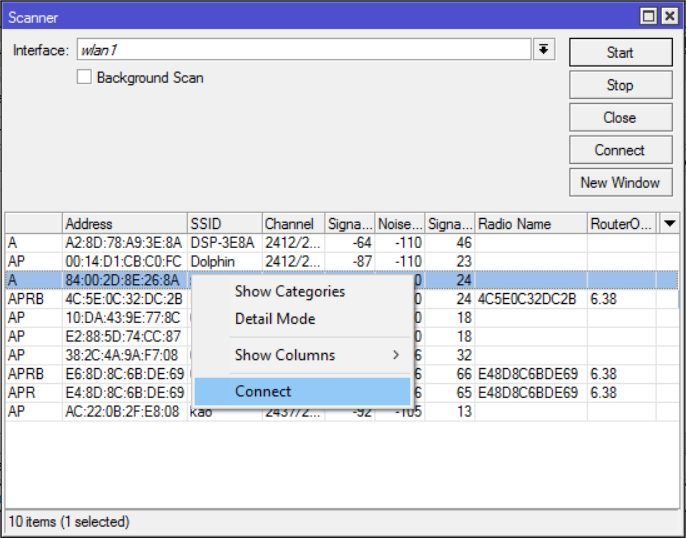
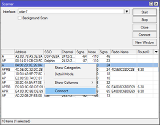
If we do not know exact wireless network we are interested in, we can enable wireless and perform a scan to see what is around.

/interface wireless
scan wlan1

Once we wither find network by scan or because we already new its name, it is time to set it up. Of course, security profile mode and all other parameters must match network you are connecting to.

/interface
wireless security-profiles add name=client-profile mode=^^dynamic-keys^^ authentication-types=wpa2-psk wpa2-pre-shared-key=^^hotel_wireless_password^^
wireless set wlan1 ssid=^^hotel_network_name^^ security-profile=client-profile frequency=auto disabled=no

This is actually one of rare situations where it is probably worth actually using GUI and wireless Scanner tool instead of getting all this sorted out manually. Regardless, if all went well, you should see upper case R next to the wlan1 interface.

As we destroyed the whole network configuration, we need to setup DHCP client on wlan1 interface so we can obtain IP. This is a nice second checkpoint as you should see the hotel’s IP address getting assigned to your router.

/ip
dhcp-client add interface=wlan1 disabled=no
address print

Now that we have client sorted out, we need to create the access point. That involves setting up a security profile, creating the access point interface on top of the existing wlan1, getting its DHCP server interface sorted out, NAT, and lastly the basic firewall.

/interface
wireless security-profiles add name=ap-profile mode=dynamic-keys authentication-types=wpa2-psk wpa2-pre-shared-key=^^access_point_password^^
wireless add name=ap-wlan master-interface=wlan1 mode=ap-bridge ssid=^^access_point_network_name^^ security-profile=ap-profile disabled=no

/ip
address add interface=ap-wlan address=192.168.89.1/24
dhcp-server network add address=192.168.89.0/24 gateway=192.168.89.1
pool add name=ap-pool ranges=192.168.89.10-192.168.89.99
dhcp-server add name=ap-dhcp interface=ap-wlan address-pool=ap-pool disabled=no

/ip firewall nat
add chain=srcnat out-interface=wlan1 action=masquerade

/ip firewall filter
add chain=forward action=accept in-interface=wlan1 connection-state=established,related disabled=no
add chain=forward action=accept out-interface=wlan1 disabled=no
add chain=forward action=drop disabled=no

/system reboot

Assuming everything went fine, after reboot, you will have your access point going through hotel’s wireless.

This setup is not necessarily the most comfortable one as every time you want to connect to new network you will have to use WinBox over the ethernet cable. And no, you cannot use access point for configuration since access point is only active if its master - hotel’s connection - is running.

Again no, you cannot do it other way round - have the access point as the main wireless interface and station as slave because you need to have station tracking for your hotel’s access point. If you setup your access point first, you will need to set its frequency to match hotel’s access point at all times. That doesn’t play well if you roam through hotel and see APs with the same name and different frequency nor it will play well if AP changes its frequency, for example, due to radar detection.

However, this setup gives you the full power of Mikrotik to use in a wireless bridge at the cost of a single device.

Me? I’ll stick to my double mAP method.

PS: Yes, you could work around the need for Ethernet cable but it gets complicated enough that it is not worth the trouble.

PPS: Yes, firewall is VERY basic.

Simple SSTP VPN Server on Mikrotik

Illustration

Few posts ago, I have gone over the procedure needed to get OpenVPN going. However, what about SSTP-based VPN?

This guide is going to assume you are to enter commands into the New Terminal window from WinBox. That way I will simply repeat commands needed instead of going through the screens. Commands are actually quite descriptive and easy to “translate” into GUI actions if that is your preference.

Prerequisite for any VPN server is to get certificates sorted. Procedure is exactly the same as for OpenVPN server setup with the slight difference being that common-name really matters. It must match either external IP or external host name - no exceptions.

For completeness sake, I will repeat the certificate creation steps here:

/certificate
add name=ca-template common-name=^^example.com^^ days-valid=3650 key-size=2048 key-usage=crl-sign,key-cert-sign
add name=server-template common-name=^^*.example.com^^ days-valid=3650 key-size=2048 key-usage=digital-signature,key-encipherment,tls-server
add name=client-template common-name=^^client.example.com^^ days-valid=3650 key-size=2048 key-usage=tls-client

sign ca-template name=ca-certificate
sign server-template name=server-certificate ca=ca-certificate
sign client-template name=client-certificate ca=ca-certificate

Depending on your router’s speed, that sign command might time-out - nothing to worry about - just wait for CPU to drop below 100%. Or alternatively check the name of certificate - template part will disappear once signing is completed.

For later shenaningans, we will need root certificate export (just move it somewhere on your computer afterward):

/certificate
export-certificate ca-certificate export-passphrase=""

Next we need a IP address pool for clients. I will assume you have your clients in some other network (e.g. 192.168.1.x) and this new network is just for VPN (notice that it can be the same pool as one used for OpenVPN):

/ip
pool add name="vpn-pool" ranges=192.168.8.10-192.168.8.99

Instead of editing the default encrypted profile, we can create a new one. Assumption is your Mikrotik will also be a DNS server. And while at it, you can create a bit more imaginative user/password (again, if you did this for OpenVPN server, you can just reuse the same profile and user):

/ppp
profile add name="vpn-profile" use-encryption=yes local-address=192.168.8.250 dns-server=192.168.8.250 remote-address=vpn-pool
secret add name=^^user^^ profile=vpn-profile password=^^password^^

Finally, we get to enable SSTP VPN server interface - first step that is actually needed if you already have OpenVPN server running:

/interface sstp-server server
set enabled=yes default-profile=vpn-profile authentication=mschap2 certificate=server-certificate force-aes=yes pfs=yes

One curiosity is force-aes flag that is officially listed as not working with Windows clients. I’ve tested it on Windows 7 and 10 without any issues. You can clear it if you play with something older.

With this, our SSTP VPN server is up and running - onto the client setup!

For client we first need to import our certificate authority and we need to do it a bit roundabout way. First we start MMC (Microsoft Management Console) using mmc.exe and to it add Certificates (File->Add/Remove Snap-in). When asked select Computer account for Local Computer and find Trusted Root Certification Authorities. Right-click on it will show Import to which we give certificate we’ve exported a few steps ago.

In the Network and Sharing Center now we can go and Set up a new connection. When asked we just select Connect to a workplace and write destination host name (or IP). Remember that it must match certificate common-name (or a matching wildcard) you gave to your server certificate.

If all steps went fine, you should be presented with user name / password prompt and off you go.

PS: Do not forget to adjust firewall if necessary (TCP port 443).

/ip firewall filter
add chain=input protocol=tcp dst-port=443 action=accept place-before=0 comment="Allow SSTP"

[2017-01-26: Adjusted certificate creation to work on RouterOS 6.38 and later] [2017-01-26: Changed key size to 2048 (instead of 4096) so it doesn’t take ages to generate certificates. :)]

Simple OpenVPN Server on Mikrotik

Illustration

Having OpenVPN server on your router is a nifty feature. However, as often with Mirotik, not all is straight forward.

This guide is going to assume you are to enter commands into the New Terminal window from WinBox. That way I will simply repeat commands needed instead of going through the screens. Commands are actually quite descriptive and easy to “translate” into GUI actions if that is your preference.

Prerequisite for any VPN server is to get certificates sorted. For OpenVPN we need main Certificate Authority, server, and client certificate. Yes, strictly speaking, client certificate is optional but let’s not skimp on security.

First we create all the certificate templates (10 years validity) we’ll need:

/certificate
add name=ca-template common-name=^^example.com^^ days-valid=3650 key-size=2048 key-usage=crl-sign,key-cert-sign
add name=server-template common-name=^^*.example.com^^ days-valid=3650 key-size=2048 key-usage=digital-signature,key-encipherment,tls-server
add name=client-template common-name=^^client.example.com^^ days-valid=3650 key-size=2048 key-usage=tls-client

For the purpose of OpenVPN server common name can be really anything. However, some other VPNs are not as forgiving (yes SSTP, I am looking at you) so it might be best to have either your external IP or host name as the common-name text. Any yes, if you have dynamic IP and you are not using your own domain, you can put *.dyndns.org there - no worries.

Created certificates will need signing:

/certificate
sign ca-template name=ca-certificate
sign server-template name=server-certificate ca=ca-certificate
sign client-template name=client-certificate ca=ca-certificate

Depending on your router’s speed, that sign command might time-out - nothing to worry about - just wait for CPU to drop below 100%. Or alternatively check name of certificate - template part will disappear once signing is completed.

With this we need to export a few files:

/certificate
export-certificate ca-certificate export-passphrase=""
export-certificate client-certificate export-passphrase=^^12345678^^

This should give you three files: cert_export_ca-certificate.crt, cert_export_client-certificate.crt, and cert_export_client-certificate.key. After copying this on computer for later I like to rename them to ca.crt, client.crt, and client.key respectively.

Next we need a separate pool of IP addresses for clients. I will assume you have your clients in some other network (e.g. 192.168.1.x) and this new network is just for VPN:

/ip
pool add name="vpn-pool" ranges=192.168.8.10-192.168.8.99

Instead of editing the default encrypted profile, we can create a new one. Assumption is your Mikrotik will also be a DNS server. And while at it, you can create a bit more imaginative user/password:

/ppp
profile add name="vpn-profile" use-encryption=yes local-address=192.168.8.250 dns-server=192.168.8.250 remote-address=vpn-pool
secret add name=^^user^^ profile=vpn-profile password=^^password^^

Finally, we can enable OpenVPN server interface:

/interface ovpn-server server
set default-profile=vpn-profile certificate=server-certificate require-client-certificate=yes auth=sha1 cipher=aes128,aes192,aes256 enabled=yes

Now finally we can copy both ca.crt and client.crt to C:\Program Files\OpenVPN\config\ directory alongside client.ovpn.

You don’t have client.ovpn? Well, one is in sample-config directory and we just need to change/add highlighted items:

client
dev tun
proto ^^tcp^^
remote ^^example.com^^ 1194
resolv-retry infinite
nobind
persist-key
persist-tun
ca ca.crt
cert client.crt
key client.key
remote-cert-tls server
cipher AES-128-CBC
^^auth SHA1^^
^^auth-user-pass^^
^^redirect-gateway def1^^
verb 3

A bit annoying step is being asked for the private key passphrase (in the addition to username/password). Mikrotik doesn’t allow export without it but fortunately we can use OpenSSL to change that:

openssl.exe rsa -in client.key -out client.key
 Enter pass phrase for client.key: 12345678
 writing RSA key

With this, your VPN connection should work like a charm.

PS: Do not forget to adjust firewall if necessary (TCP port 1194).

/ip firewall filter
add chain=input protocol=tcp dst-port=1194 action=accept place-before=0 comment="Allow OpenVPN"

PPS: Do check SSTP guide too.

PPPS: If you’re on RouterOS 7 you might want to check this guide for UDP.

[2017-01-26: Adjusted certificate creation to work on RouterOS 6.38 and later] [2017-01-26: Changed key size to 2048 (instead of 4096) so it doesn’t take ages to generate certificates. :)] [2017-02-25: Changed example to use AES-128 for lower CPU usage on router.]

Local Host Name Resolving Under Windows With Mikrotik's DNS

Illustration

As I switched all DNS resolving to my Mikrotik router, a curious problem appeared. I couldn’t access my main file server using its short name anymore.

That is fine, I thought. If I go to IP -> DNS and I add Static entry for it. And so I did and everything worked when I tested it. From Linux machine. From Windows 10 machine you ask? Nope - I couldn’t access it still. I try ping and it complains. I try nslookup and it works. Interestingly, an entry with a domain (e.g. server.thing) would work with both. It was just short names that wouldn’t behave.

To make long story short, fix is to force Windows to use longer names even for single word lookups. To do this, we can employ magic of DHCP’s domain-name setting conveniently available under DHCP network setup. If this is provided to Windows host upon IP address assignment, it will append all single word host names with that DNS suffix and, provided you defined static DNS host entry with that full name, Windows will work happily ever after.

Downside of this solution is that you need to have both long and short form (e.g. server and server.network) defined for mixed Windows/Linux environments. Yes, you can create a regex to cover both but it will look ugly (e.g. ^server(.network)?$). I personally simply define host two times - looks nicer. ;)

Root issue is just another leftover from NBNS/WINS resolver era - something nobody uses on any normal network but somehow Windows still thinks of it as an appropriate default behavior. Annoyingly some components are built smarter so, depending which tool you use, you can chase damn Schrödinger’s cat all day long…

Remote Passwordless SSH/RSA Login Into Mikrotik

It all started with the need for backup. I had to do two things. First create a backup user with read-only access and then to automate gathering of exported configuration using SSH. And, as a twist, SSH would need to use RSA - something WinBox started supporting only recently (since 6.31).

The easiest way to configure this is to enter commands into New Terminal from WinBox. I will simply repeat commands needed instead of going through the screens. Commands are actually quite descriptive and easy to “translate” into GUI actions if that is your preference.

Before creating user itself we need to create a group without any rights, followed by user creation:

/user
group add name=backup policy=
add name=backup group=backup

With the user in hand, we should get key authentication going. Do notice that key.txt contents should be the public key for use with login. How to generate it is out of scope but just google PuttyGen and you can find a lot of information about this. In any case, we can set publick key for user by using the following commands:

/file
print file=key.txt
set key.txt contents="^^ssh-rsa ...^^"

/user
ssh-keys import public-key-file=key.txt user=backup

After assigning key to a user, we can give it appropriate rights - in my case those were ssh and read. Do notice that policy could have been set while creating group but that would allow user to login without any password until SSH key was set. While window is short and chance is really remote, I prefer to avoid it:

/user
group set [find name=backup] policy=ssh,read

If everything has been done correctly, you can log into router using your RSA keys and you can run export command to gather current configuration.

PS: If you are limiting MACs to be used with SSH beware that Mikrotik supports only hmac-sha1.

Isolating Mikrotik LAN Ports With Queue Support

When I last time did LAN port isolation, it seemingly ended with a success. And yes, I have ran with that config for a while without problems. However, at one point, I decided to implement bandwidth limits per port using queues. However, a speed test has shown that while download speed looking from WAN side was throttled, my maximum upload speed wasn’t observed.

I won’t get too much into why it is so. It’s sufficient to say you cannot set upload speed on interface if it is a slave. Guess what, interfaces belonging to a bridge are slaves. It doesn’t matter if you place each interface in its separate bridge - as was my first attempt - while your upload will be throttled, your download limiting will not work.

The only configuration I’ve found working was to have each interface manage its own network - thus each being the master.

The easiest way to configure this is to enter commands into New Terminal from WinBox. I will write commands assuming all bridges, their ports, and each mentioned section are completely empty as we start.

First we need to give a separate IP to each interface facing our internal LAN:

/ip address
add address=192.168.1.1/24 interface=ether2 network=192.168.1.0 disabled=no
add address=192.168.2.1/24 interface=ether3 network=192.168.2.0 disabled=no
add address=192.168.3.1/24 interface=ether4 network=192.168.3.0 disabled=no
add address=192.168.4.1/24 interface=ether5 network=192.168.4.0 disabled=no

Next we define multiple DHCP pools - in this case 4 of them:

/ip pool
add name=pool1 ranges=192.168.1.10-192.168.1.99
add name=pool2 ranges=192.168.2.10-192.168.2.99
add name=pool3 ranges=192.168.3.10-192.168.3.99
add name=pool4 ranges=192.168.4.10-192.168.4.99

Of course, adding a separate DHCP server for each of these pools is needed:

/ip dhcp-server
add name=server1 interface=ether2 address-pool=pool1 disabled=no
add name=server2 interface=ether3 address-pool=pool2 disabled=no
add name=server3 interface=ether4 address-pool=pool3 disabled=no
add name=server4 interface=ether5 address-pool=pool4 disabled=no

DHCP network for each follows:

/ip dhcp-server network
add address=192.168.1.0/24 gateway=192.168.1.1 netmask=24
add address=192.168.2.0/24 gateway=192.168.2.1 netmask=24
add address=192.168.3.0/24 gateway=192.168.3.1 netmask=24
add address=192.168.4.0/24 gateway=192.168.4.1 netmask=24

Quick stop to verify routes is in order. Assuming you all is done correctly four new dynamic routes should appear (it is ok for disconnected ports to have distance 255):

/ip route print
 Flags: X - disabled, A - active, D - dynamic,
 C - connect, S - static, r - rip, b - bgp, o - ospf, m - mme,
 B - blackhole, U - unreachable, P - prohibit
  #      DST-ADDRESS     PREF-SRC         GATEWAY      DISTANCE
  0 ADS  0.0.0.0/0                        192.168.0.1         1
  1 ADC  192.168.1.0/24  192.168.101.250  ether2              0
  2  DC  192.168.2.0/24  192.168.102.250  ether3            255
  3 ADC  192.168.3.0/24  192.168.103.250  ether4              0
  4 ADC  192.168.4.0/24  192.168.104.250  ether5              0
  5 ADC  192.168.0.0/24  192.168.0.14     ether1              0

Assuming you don’t have NAT masquarade setup from before, let’s setup one now. If you do have it already in IP Firewall NAT, simply skip this step:

/ip firewall nat
add action=masquerade chain=srcnat out-interface=ether1 disabled=no

After all this we can finally add traffic limiting queues. In my case the first two ports didn’t have any limits, third had 1 Mbit/s upload and download, and the last interface had 128 kbits/s upload and 256 kbits/s download:

/queue simple
add name=queue1 target=ether2 max-limit=0/0
add name=queue2 target=ether3 max-limit=0/0
add name=queue3 target=ether4 max-limit=1M/1M
add name=queue4 target=ether5 max-limit=128k/256k

To isolate LAN ports we again use the firewall rules allowing the new connections only toward ether1 (WAN) interface:

/ip firewall filter
add action=accept chain=forward connection-state=established comment="Allow established"
add action=accept chain=forward connection-state=related comment="Allow related"
add action=accept chain=forward out-interface=ether1 comment="Allow WAN"
add action=drop chain=forward comment="Drop everything else"

PS: There is quite nice guide at Networking For Integrators. They use a quite similar approach for the purpose of segregating multiple networks.

Enabling HTTPS on MikroTik

Mikrotik and its WinBox interface are virtually inseparable. Most people use it without thinking of any other option. However, Mikrotik supports also has (quite a good) HTTP interface and it also supports a (disabled by default) HTTPS access.

Enabling HTTPS is unfortunately not a straightforward experience.

The easiest way to configure this is to enter commands into New Terminal from WinBox. I will simply repeat commands needed instead of going through the screens. Commands are actually quite descriptive and easy to “translate” into GUI actions if that is your preference.

For HTTPS to work we need to create two certificates, master and apprentice. Ok, actually we need root and HTTPS certificate but master and apprentice sounds much cooler ;):

/certificate
add name=root-cert common-name=MyRouter days-valid=3650 key-usage=key-cert-sign,crl-sign
sign root-cert
add name=https-cert common-name=MyRouter days-valid=3650
sign ca=root-cert https-cert

With certificate signed, we just need to assign it to www-ssl service and enable it, while disabling non-https variant:

/ip service
set www-ssl certificate=https-cert disabled=no
set www disabled=yes

And that’s it. Now you can access your router via HTTPS.

PS: Never use unencrypted interface like HTTP or FTP toward your router. Your password will travel plain-text and risk is not worth 5 minutes it takes to enable TLS encryption.

Adding Mikrotik DDSN as a Subdomain

Illustration

If you need remote access, one of things you’ll notice about Mikrotik devices is there is no support for DDNS. Yes, you could always create a script for it but there is nothing built-in.

However, Mikrotik does offer quite similar functionality out-of-box for a year now. In Cloud menu you just select DDNS enabled and Mikrotik your public IP will be located at <serial>.sn.mynetname.net. It is not as nice as having custom name with DynDNS, but usable nonetheless.

However, if you have your own domain, you can make it a bit more friendlier. Find where you can edit DNS entries at your registrar (Manage Domain with DreamHost) and add a new CNAME entry. For name you can put whatever you want and for value put Mikrotik’s DNS name (<serial>.sn.mynetname.net).

After a few minutes (damn DNS propagation :)) you’ll see your DNS entry working.

PS: You can verify status with nslookup myname.mydomain.com.