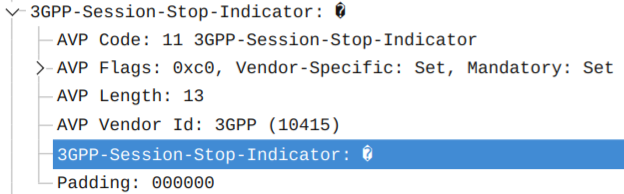
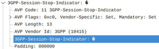
AuxPower1U: Fan Controller

This is post 8 in the series (previous: Fan Controller Design).

This post is sponsored by PCBWay.
Check and/or participate in their PCBWay 7th Project Design Contest.


With all design decisions done in the previous post, it was time to get PCBs made. As PCBWay was interested in the project, it was an easy choice. :) That said, if you go to my GitHub, you'll notice I have many more electronics projects that I haven't gotten around to write about and they are not sponsored by anybody (patience of my wife, excluded). Yet still, I quite often go for PCBWay anyhow.

In this particular case, PCB was simple enough that any manufacturer would be able to produce it. Or so I thought before PCBWay contacted me due to an issue. You see, my KiCAD export workflow relies on a script. Thus, usually results are quite repeatable. So I thought it was a false positive. But nope - PCBWay was right, I had some of my layers swapped - darn copy/paste when I was updating the script. I am not saying that some other manufacturers wouldn't catch this, but it wouldn't be a surprise if I got wrong PCBs due to this mistake on my part. With PCBWay, I never managed to sneak an error by them.

Once the board arrived, I started creating firmware and the first step was generating the 25 kHz PWM signal. A few initialization settings later, I had a perfect 50% duty cycle signal. So I connected my fans only to be surprised by their noise. I mean, I expected some noise - those are server fans after all. But I also expected that noise at 50% wouldn't be that bad. Then again, they did move a lot of air, so I decided to bring PWM down to 10%. And... fans were equally loud and moved an equal amount of air.

It took me a few visits to the fan datasheet to notice one discrepancy. Unlike normal PC fans that have PWM on wire 4, Delta's have PWM on wire 3. Wire 4 is the tachometer output. Why the heck they opted for a non-standard pinout is beyond me; but I am sure there is some historical reason behind it. In an case, I swapped wires to be in a standard fan arrangement and what I got was almost silent cooling.

Since I don't know how much cooling I'll need, I opted to have 3 fans together. And while this was probably an overkill because these beasts move air like there's no tomorrow, it also enabled me to keep fans at low speed by default, going up in speed (and noise) only when temperature requires that.

So, after consulting the power supply datasheet, I decided on the following curve:

  • 10% speed until it reaches 40°C
  • speed linearly increases up to 50% between 40-60°C
  • stay at 50% up to 70°C
  • if above 70°C, go to full 100%

The idea behind this is to balance fan noise and cooling, unless we get into temperatures that might jeopardize power supplies. Since my selected power supplies shutdown at 85°C, giving them some cooling buffer seemed like a good idea. Mind you, I don't expect them to ever reach that temperature, but it's nice to know that fans will do their best, if they do.

Those reading fan datasheet will notice that, while fans work just fine at low RPM, they do require 30% PWM to start. Such requirements are the reason why, on servers, you will hear fans running at 100% for a few seconds before slowing down to normal speeds - they have to ensure successful startup. For me, I didn't need to be that aggressive but I still wanted to give them a decent chance. So, every time power is applied, the fan controller will push 30% PWM out for 500ms, followed by a 250ms burst to full speed. After that, speed goes down to 10% and temperature control loop takes over. Just to be fancy, not all fans spin at the same time, but are offset by 250ms. There is literally no reason for this other than it giving an interesting sound profile.

I mentioned temperature a few times now, so you might be wondering how I am measuring it. The nswer is the MCP9701A temperature sensor. It gives you a temperature range from -40°C all the way to 125°C with a slope of 19.53 mV/°C. While this number looks a bit crazy, it actually translates almost perfectly into 4 bits (10-bit ADC) per °C if you use a 5V reference input. Since I don't expect sub-zero temperatures, my temperature calculation is as simple as removing 82 bits from the raw reading to make the scale start at 0°C and then dividing the whole thing by 4 (those wanting to optimize would simply use shift operation here).

Now, PIC12F1501 does have an internal temperature sensor you can use. And that would work in a pinch, but it's not without its drawbacks. The first one is that it measures the die temperature, that varies not only due to external temperature, but also based on what's happening in microcontroller itself. If you drive a lot of things, your reading will be higher even though external temperature remains the same. Other, probably related issue, is its instability. It's not what you would call a precise sensor to start with, but then you'll have to deal with smoothing out data coming out of it because it can change value by couple degrees in mere seconds. It's not that you cannot filter those things out - an long-period averaging will take care of that - but it's just a pain in the butt. Thus, I went with a proper temperature sensor.

There are some things I intentionally omitted. But one that causes the most doubt is speed readback. There are two ways I could have gotten that feature for free. One is to only have 3 channels, which would allow me to use 3 pins to control PWM and 3 pins to read back the speed. Yes, that would also mean switching to the internal temperature sensor, but I could make that work. Other way of doing that would be to have just 1 PWM signal going to all 4 fans, 4 speed inputs, and that even leaves 1 pin for a temperature input. But then the question becomes "why".

Since this board is a standalone thing, there is literally no way of letting the user know that one fan is stuck. Yes, it could have enabled an even smoother startup (since I can verify it's started instead of blindly going to 30%) but, other than that, there is simply no use for it. It would only make sense if I went onto a bigger microcontroller so I can have UART or I2C connecting it to the rest of the system, and I think that would be overkill.

And no, the system as a whole will not kill itself if fans stop spinning. My other part is controlling power supplies and that board will have its temperature sensor. If temperature goes dangerously high (e.g. because fans are not spinning), that board is in a situation to either stop overloaded power supply, inform the user, or do whatever I deem necessary in that situation. After giving it a lot of thought, I decided to keep it simple.

Source for PCBs and firmware can be found on project's GitHub pages. And in video below you can see the fan controller startup in action.

Leave a Reply

Your email address will not be published. Required fields are marked *