The New Firmware
With all the changes in the AuxPower1U project, it was inevitable that firmware will change too. However, some changes were in order.
First was in regards to my PhotoMOS setup. While 6A AQZ202G PhotoMOS supports all I need, I only had 2 of them handy (actually, I started with 3, but we won’t discuss my testing procedures). So, I filled rest of channels with 4A CPC1706Y PhotoMOS. Why am I mentioning hardware in the firmware part? Well, part of my firmware is handling safety cutoffs. And those are not the same between all channels now. Yes, these are still hard-coded because I am too lazy to create GUI. But they are separated into a function so changing them shouldn’t be a chore. The first three channels have 4A safety limit while the last two have full 6A.
Another change was turning off display after a period of inactivity. While having it always visible was handy, it did cause degradation in cheap displays. After months of having it on with the previous display, burn-in was becoming a problem. Since I rarely check that display, it seemed like a good idea to simply turn it off until button press is detected. Cheap firmware solution for a hardware problem.
And lastly, I changed how output pins are handled. Originally, I handled them via I2C expansion which works like a charm. But, that introduces an extra device in what you might call a critical path. Since, due to other changes, I did have 5 pins available, in the new revision output is controlled directly from microcontroller without going to the expander board. As to preserve compatibility with the previous board, code sets both I2C and pins directly. That way both revisions can work on the same firware.
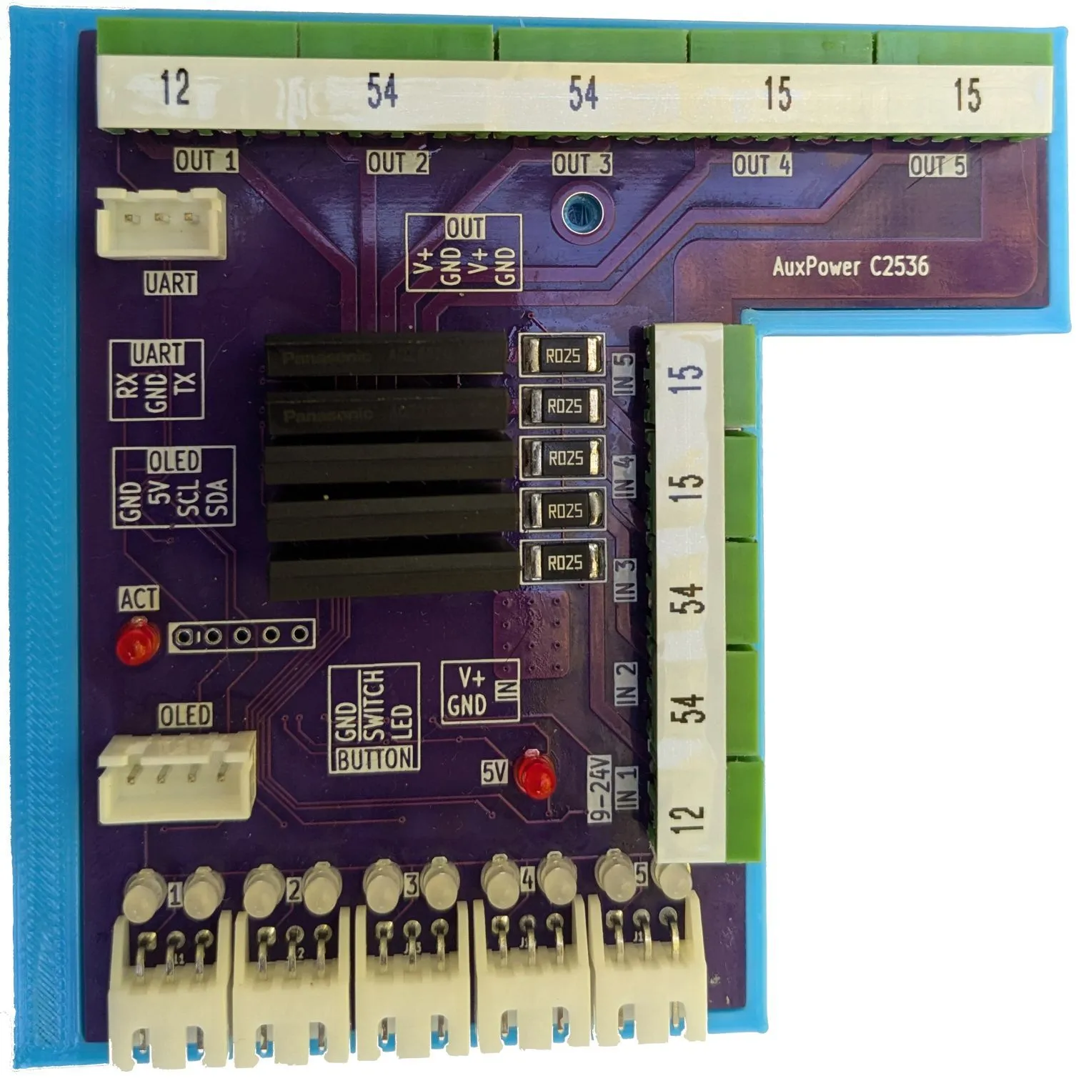
With all this, my AuxPower1U revision C was ready for “production”.