AuxPower1U: Triggering Dell
This is post 4 in the series (next: Power Supply Selection, previous: Case Selection).
One action item mentioned way back in the first post, was discovering if a Dell Optiplex 3050 Micro can handle voltages lower than its specified 19.5V. However, you cannot just check that by plugging in any old power supply. No Sir, you need to have a 19V charger blessed by gods and naked virgins who dedicated their life to making sure your Dell equipment is not using impure power like those other peasant computers do.
However, since I am unworthy of such service, I decided to see about bypassing the same for three reasons. The firs2024t one is that it makes my life so much easier if I can use any old charger in case my current charger dies. Secondly, it really messes with my goal of consolidating power supplies if I need to take special care of Dell.
Before I went onto deciphering the charger protocol myself, I decided to check if someone had already done the work. And, wouldn’t you believe it, someone did. Even better, the author provided all the information one might need. The only thing I had to do was to make a PCB. So make a PCB I did.
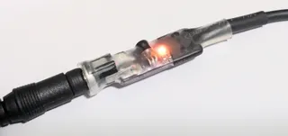
The final board consists just of a resistor in series with the EEPROM data line and a zener diode for overvoltage protection between the data and ground. The value of the resistor is not really important but original charger uses 330 so that’s what I went with. Zener is also not critical so I went with 5.1V one I had laying around - go, mini-MELF, go!
The main part is a 1-wire EEPROM memory, either DS2501 or DS2502. And yes, you can program that EEPROM yourself, but there is actually a source of preprogrammed memory on AliExpress. That is way easier than dealing with 12V pulses programming this memory requires. There are some reports suggesting you can use DS2431 (with much simpler programming model) but buying preprogrammed stuff was easier.
As for the Dell connector, I was originally planning to cut the existing cable but Amazon had some pigtails available so I opted to use them and keep my original charger for emergencies. On the barrel connector side I found that a DC 2.1x5.5mm connector intended for panel mounting has spacing that fits a 1.6mm PCB perfectly.
With PCB and all parts ordered, the only remaining work was to assemble, wrap it in heat shrink, and finally test whether 3050 is properly charging at 15V. Will it? Well, it will!
Based on the old method of “try and see what happens”, I could power on my Dell starting as low as 13V. While that was the lowest voltage it booted on but I found it would ocassionally “stutter” a bit. However, when I bumped it to 14V, all looked the same as when running at the official 19.5V. For all practical purposes, you can view the Dell Optiplex 3050 Micro voltage range as 14-20V.
And yes, all standard disclaimers apply, especially given that it’s a test sample of one. For this use case, I only care about my setup, so this is sufficient. However, I am willing to bet that pretty much all other similar Dell machines behave the same.
In any case, this smalll board enables me to emulate Dell charger at lower voltage, thus allowing use of 15V power supply. This gives me access to a more common voltage in embeeded electronics (way more common than 20V that’s usual for laptops) and it also proves that both my NUC and Dell can both drink power from the same faucet.
