Overthinking the LED Blinking
The very first thing I add to every piece of hardware I make is an LED. It not only signals that the device is on, but you can also use one to show processing or even do some simple debugging. What I often go for is a simple resistor+LED pair. And here is where the first decision comes - do I go for high-side or low-side drive?
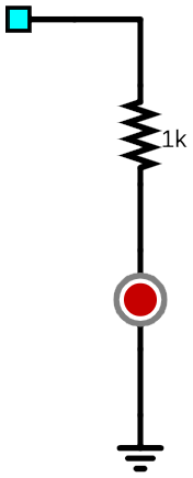
High side drive is when your output pin goes into the anode of the LED. The exact resistor location doesn’t really matter, and either before or after the LED results in the same behavior. When your pin goes high, the LED lights up. When the pin goes low, the LED turns off.
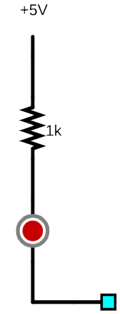
Low side drive is pretty much the same idea but with logic reversed. When the pin goes low, the LED turns on, while the pin going high turns it off.
With both being essentially the same, why would you select one over the other? Honestly, there is no difference worth mentioning. It all goes to personal preference and/or what is easier to route on the PCB.
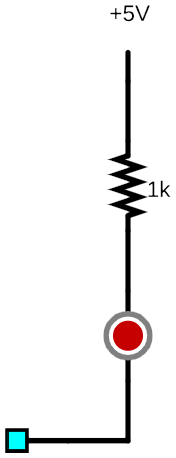
For open-drain LED control we make use of the tri-state output available on most microcontrollers (high-Z state simulated using a switch). In addition to the standard low and high setup, we have an additional one sometimes called high-Z (or high impedance). In Microchip PIC, this is done by manipulating the TRIS pin. If the output TRIS is 1 (high-Z), the LED will be off. If TRIS is 0 and the output is low (the only valid open-drain state), the LED has a path to the ground and lights up.
This is quite similar to the previously mentioned low-side drive and has pretty much the same effect but with a slightly different way of controlling the pin. I would argue that both are essentially the same if your circuit uses just a single voltage. Where things change is when you have different voltages around as open-drain will work for driving LED on any rail (ok, some limits apply) while low side drive will not turn off fully if, e.g., you are controlling 12V LED with a 5V microcontroller.
But this open-drain setup got me thinking whether I can have use something similar to have LED be on by default? Why, you wonder? Well, my first troubleshooting step is to see if input voltage is present. My second troubleshooting step is to see if microcontroller is booting. Quite often, those tasks fall onto two different LEDs. If I could have LED on by default, that would tell me if there’s any voltage to start with and then blinking boot sequence would tell me microcontroller is alive and programmed.
Well, there is one way to do it, and I call it default on open-drain. Unprogrammed Microchip PIC has pins in tri-state (high-Z) configuration. Thus, current will flow through LED as soon as voltage is applied. However, if pin goes low, current will flow to the pin and thus LED will go off. Exactly what we wanted.
Albeit, nothing comes without the cost and here “cost” is twofold. The first issue is current consumption. While our “on” state is comparable to what we had with other setups, our “off” state uses even more current. For blinking it might not matter but it should be accounted for if you have it off for longer duration.
Second potential issue comes if our ping ever goes high since that will have LED pull as much current as pin can provide. While Microchip’s current limiting is usually quite capable, you are exceeding current limit and that’s never good for a long-term PIC health. And chips that have no current limiting are going to fry outright. It is critical for functioning of this LED setup that the only two states are ever present: either low or high-Z.
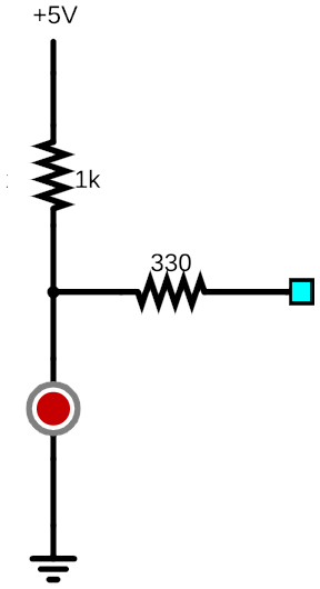
To avoid this danger, we can do the same setup using two resistor split. Assuming both resistors together are about the same overall value, in “on” state this circuit matches what we had before. In “off” state, we unfortunately increased current even further but, if we ever switch pin to high, we are fully protected. Even better, this setup allows for three LED states: “on”, “off”, and “bright”. This feature alone might be worth increased current consumption.
In order to deal with higher current consumption, we could reorganize resistors a bit. This circuit behaves the same as the previous one if microcontroller’s pin is high-Z (or not present). If microcontroller pin goes high, “bright” state gets even brighter as you’re essentially putting two resistors in parallel.
When pin goes low, we have those resistors in series and thus current consumption, while still present, is not exceedingly higher than what “on” state requires. And yes, having made what’s essentially a voltage divider does mean that LED is not really fully off. However, it goes dark enough that nobody will be able to tell the difference when blinking starts.
Which one is best?
Well, I still use a bog-standard resistor-LED drive the most (either low, high, or open-drain). It’s simple, it’s fool-proof and definitely has the lowest current consumption among examples given. However, for boards where remote debugging is a premium but space doesn’t allow for bigger display, I find that having three brightness settings at a cost of a single resistor is quite a useful bargain.


