CAN Bus Decoding Using PicoScope
When it comes to CAN bus protocol decoding, beating PicoScope is hard considering that even the cheapest 2000 series member has full support for it. Converting such scope to one with the floating ground is as easy as unplugging your laptop (or running your desktop of an UPS’ battery). However, there are a few issues you might want to avoid.
The very first step would be to properly trigger on the CAN bus message. Reasons for this are twofold. If there is any issue with your signal, this will allow you to catch it early so you can sort out basic electrical stuff before going on the higher level. Secondly, reliable triggering will help software decoder properly detect message start.
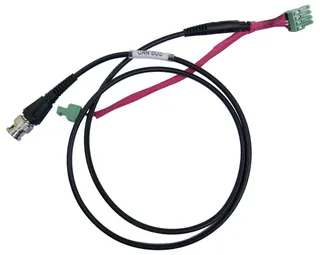
While exact trigger level might depend on the exact use case, in 95% of cases we are talking of 5V differential signal. Roughly speaking, your CAN L (low) signal will be either at 2.5 V or 0 V logical level and your CAN H (high) signal will be at either 2.5 V or 5 V level. Since signal between those two lines is mirrored, you only need to probe one of those two lines. I usually select L but that’s just because I already have cable made for it. All instructions are essentially the same whichever polarity you select. Good starting trigger level for low line is 2 V (3 V for high line). If your resting signal is further away from 2.5 V that would either point to termination issue or gross impedance mismatch and you should sort “electricals” first before continuing further.
I like to set pre-trigger level to 5% as it allows me to use most of the screen for actual signal. To receive the maximum screen real estate you might be tempted to use 0% pre-triggering but I find seeing a bit of signal before my CAN message does help if you have a busy bus. Even better, this also allows you to ignore trigger edge setting completely (should be falling for low line).
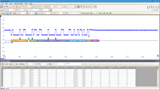
Only once you can reliably catch your CAN signals, you can add serial decoder - Tools / Serial Decoding / Create / CAN. After selecting channel with your signal (named Data on this form), you will reap the benefits of getting triggers right. First and foremost, you should have bitrate set correctly as soon as channel is selected. More over, your threshold level should be automatically calculated from the signal. Yes, you can manually set it to 2 V but Murphy says you’ll forget it and then be confused as why decoding has errors or even misses a message completely. Lastly, you select High or Low setting appropriately depending on the line you are probing.
Congratulations! If all went good, you have just successfully decoded CAN bus message.

