Longwave Fun (part 2; aka Standalone)

This is a part 2 in my WWVB time signal series (part 1, part 3).


After I essentially reproduced TxTempus project in PCB format, I thought to myself - what if I remove Raspberry Pi portion and get it working over USB?

Illustration

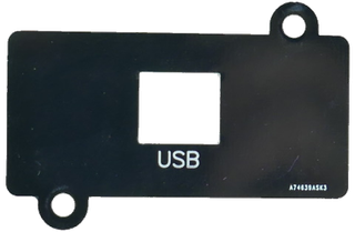
Choosing the enclosure was the easiest part. I saw this project fitting perfectly in Hammond 1593DBK. Its long format gives me enough space for antenna while its shape just calls for a watch to be placed around it. Even better, if I cannot get the original, there is an extremely similar HP-3653-B from Bud Industries.

Mind you, they are not exactly the same. For example, one has screws on the top while other has them on the bottom. Bud has just a smidgen shorter length. Even the shape of the panel is slightly different. So you cannot really just get PCB designed to fit Hammond directly into the other. However, if you are aware of those things, you can abuse tolerances a bit and design both board and panels that fit either case without any noticeable difference.

At first I decided to have a 0.8mm PCB so my favorite type-C can be easily soldered. PCBWay generously offered to get them to me for free. While this wasn’t the first time I ordered from them (and yes, I paid for boards more times than I got them free) it was the first time I used them for 0.8mm board.

Illustration

They have a crazy amount of options and I keep changing my mind about how user-friendly this is. For some projects it makes sense to go over many options and fully customize everything but having all options on one page is slightly overwhelming and selecting the “wrong” option can really increase the price. If you don’t catch it immediately, it might be hard to figure out which option changed the price. Fortunately, both 1.6mm and 0.8mm are the same price. While some colors do involve extra cost, there is a fair selection of colors you can get for free. I went with green just because it ships faster.

For this project I didn’t go with any extra options and the only thing I missed was gold plating. While their HASL surface was leveled and I didn’t have any issues soldering 0.65mm SSOP components, the “golden” ENIG finish is nicer. However, $35 price increase for such finish seemed excessive and was not worth it for me.

When it comes to how the finished board looks, a basic green PCB is not a looker. While normal 1.6mm boards are a bit translucent, going to 0.8mm makes it excessively so. I cannot say I’m a fan of how it ended up looking and I would go with any other color (love the blue they have), even if it means a few days more.

Also worth it, is the removal of an internal product number PCBWay places on their boards unless you pay the extra $3. The placement itself was unobtrusive and sensibly done (way better than a few years before) but I am not sure if it was due to the care or pure coincidence. Even so, I think not having that number should be the default (and free).

My board didn’t push any limits (8/8 mils) so I didn’t really expect any issues. And I must say I saw none. The quality was good with traces looking really even. Based on just that I can bet their process is quite better than 6/6 they offered as a default. Either way, hand soldering 0.65mm SSOP was not troublesome at all. Not only traces and their solder masks were perfectly aligned but also surface didn’t have any serious leveling issues. I did notice there were some leveling artefacts (more on those later) but they seemed to be purely visual.

Interestingly, something went wrong with board sizes once I uploaded gerbers and my board suddenly became smaller as the order was placed. Their support did notice the same and we managed to sort it out but it caused a small delay. And yes, it was repeatable as board I ordered some time later (non-sponsored) had the exactly same issue. It might have been that their parser had issues with my DipTrace gerbers but I didn’t notice anything suspicious in them.

In any case, the boards arrived quickly. Some might say too quickly as I was still waiting for my microcontroller of choice - PIC16F1454. And I waited. And waited. Yep, I got hit by a chip shortage. But eventually Microchip came through (yes, I had to order directly from them) and the chips were in my hand.

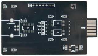
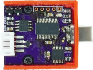
PCB design itself was reasonably simple and only about a fifth of board was used by components. The heart was already mentioned 16F1454 with an USB connector on one side and an antenna output on another. And I simply love this microcontroller.

If you want to make a serial USB device, it’s hard to get it easier than this. The only extra components you need for everything to work are two capacitors; one for general decoupling and one for the built-in USB module regulator. No external crystal, voltage regulator, nor USB pull-ups. That leaves fair 9 pins for general I/O.

Considering I just needed USB communication (D+ and D- pins), PWM module to generate 60 kHz, one output to modulate antenna signal, and another to blink a LED, even this microcontroller was more powerful than needed. However, if I needed some other features (e.g. ADC), its pin-compatible brethren - 16F1455 and 16F1459 - would allow for some growth before going to a completely different device.

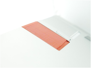
The most notable board feature is, of course, its rectangular PCB antenna. First of all you should understand that realistically you cannot create a good 60 kHz antenna on a PCB. For such a low frequency you need a LOT of wire and this PCB is way too small to fit so many loops. Even if I could fit all these loops, a PCB is not a friendly environment for it. Not only putting wire loops in a close proximity will make an inductor but it will also make a capacitor and a decent resistor.

Even if you cajole inductance and capacitance to get it to resonate at a right frequency, the amount of resistance all those trace loops have would force us to use a proper antenna driving circuit and not just a few resistors you see here. Even with all that, the imperfections in PCB process would make it impossible to retain all parameters from board to board as even the smallest trace change would throw it out of whack. And remember, we’re talking here about impractically big PCB to start with.

However, since I was intending to use this antenna in a close range, a lot of things don’t matter. Having such a huge mismatch actually helps with preventing signal going to far and messing with devices further away. It also doesn’t matter if antenna has solder mask removed or not. For this board I decided to go with solder mask removed but looks are literally the only reason for that decision. At 60 kHz this solder mask simply doesn’t change anything.

Illustration

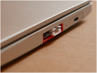
While waiting for components to arrive, I also decided to trim board a bit and make it easier to solder as not everybody likes SSOP and a type-C connector. This variant was a standard 1.6mm, slightly shorter in length, and with some components moved around a bit. And yes, I got it too from PCBWay but I paid for it with my own money . Regardless, the service I experienced was the same (including support for gerber size issue). The only change was a definitely nicer blue color - well worth extra few days of waiting if you ask me.

One extra thing I noticed about the blue board is that antenna looks much nicer and more leveled when compared to the green PCB. While the green board seemed leveled enough, on photos (or if you turn it slightly under the light), antenna has what looks as a “wave” across its surface. The blue board has the antenna surface looking much more leveled and without such artefacts.

I did check boards I previously ordered from PCBWay and I don’t see similar issues. My best guess is that their HASL leveling is not really optimized for 0.8mm boards and when you combine this with a slightly transparent (and thus less forgiving) green board you get visually worse result. Mind you, I only noticed it once I took photos under bright light so it’s really not a big deal.

In any case, with the board ready, it was time to do the firmware…


Please note I have received PCBs for this project for free from PCBWay and they are also the current sponsor of my website. They didn’t request anything specific for me to say and all opinions given here are mine and mine alone.

Longwave Fun (part 1; aka HAT)

This is a part 1 in my WWVB time signal series (part 2).


Illustration

I have been aware of “atomic” clocks and watches for a while now. Those devices rely on WWVB signal (at least in USA) for occasional time synchronization. Between two synchronizations they depend upon a standard quartz crystal to keep time. This allows for decent accuracy almost assuring time is always within a second of precision.

So, this year I decided to jump on that particular band wagon with a Casio Lineage watch. And I was immediately hit by a disappointment. While watch itself was exactly what I wanted, I simply couldn’t get it to receive and decode WWVB signal during the day. Night was slightly better and I could get it synced in the wee hours. And yes, night-time synching is what watch does anyhow and for any normal person that would suffice. But me? I wanted to play with it.

So I went searching for a WWVB transmitter. And it took no time to find Radio time station transmitter by HennerZeller. It worked wonderfully using nothing more than three resistors and a loop of wire. Instead of leaving the perfection alone, I decided to mess a bit with it.

First of all, I decided to put all components of HennerZeller’s design onto a PCB. Already with this change things got even simpler as the only external element was the antenna wire. So I attempted to remove even that using PCB trace. And here comes the first issue - if you want to make a proper antenna for WWVB at 60 kHz, you need quite a long trace. About 1.25 km for the quarter length. A bit too much for a PCB.

However, same principle as in the original design applies. If you’re ok with making a really bad antenna, any loop will do. And bad antenna has unexpected benefit - it will limit range of transmitter. Since we want to keep emissions under 40 μV/m as measured at 300 meters in order to keep FCC happy, having an imperfect antenna is really a good thing. Moreover, since watches were designed to work with weak signal, better antenna might cause issues at close range.

It did take me a few tries to figure out the exact geometry to make it work. I found that 13 loops in rectangular area allows for up to 10-20 cm (4-8 inches) of working distance. If more distance is required, PCB also includes a connector for external antenna. While transmitting longwave is troublesome, one could look into a loop stick or even a spiderweb antenna.

When it comes to PCB, one thing that immediately grabs attention is its wonky shape. Overall dimensions were clear to start with as I wanted to match Raspberry Pi zero footprint. And as long as one makes 65x30 mm rounded rectangle PCB, you have it. Since full size Raspberry Pi can take smaller boards, one would think that there’s no need for messing with it further. Until you try to put it into the official Raspberry Pi case.

Due to how the official Raspberry Pi case connects together, rectangular PCB hits side pillars and prevents it from closing. Further more, there is a camera connector underneath it so notch is needed to allow easy routing. Due to both these issues, the actual PCB got a few curves and a slim down on sides where it would interfere thus giving it the final shape.

The end result is a WWVB transmitter fully compatible with HennerZeller’s design and software fitting nicely into an official Raspberry Pi case.


PS: While this device complies with FCC rules for low power transmitters, that doesn’t make it legal in every other country. Do your research before using it._

PPS: If you’re interested in building your own, you can grab source files from GitHub or purchase kit here.

Visual Studio Code Extensions

I switched to Visual Studio Code for my text editing needs a while ago. While not perfect (still no darn CR support), I find it working well for me. However, considering it has a really nice extension model, it would be shame not to improve it a bit. So I made a few extensions of my own.

Render Line Endings

One thing I missed the most was to see line endings. Call it a habit from old python days or call it the craziness, but I often work with all whitespaces shown. And VSCode has a beautiful support for showing whitespaces within the line. But somehow, it won’t show line endings which are whitespace characters too in my book.

Idea of this extension is to work in tandem with the default rendering of whitespace characters and simply add the appropriate character at the end. Now, due to some design decisions in VSCode, extension will never be perfect. For example, VSCode normalizes the file upon loading to use only a single line ending. By the time my extension gets a stab at parsing, the original line ending is already gone. Even worse, CR line ending is still not supported and ticket is going nowhere.

That said, in 95% of cases, one is only dealing with a single line ending anyhow and extension can not only show it but it can also highlight errors (e.g. non-default line ending; i.e. CRLF when LF is expected) or extra trailing whitespaces.

It wasn’t the first extension of this type and it probably won’t be the last one. But it is (currently) the most popular and I’ve gone through a lot of efforts to make it the fastest too. Yes, it might be the same speed (or maybe even a bit slower) on small files but if you load a big file, all changes. My extension is pretty much the only line ending highlighter that doesn’t load the whole darn file in one go but does its work incrementally.

Unicode Code Point

When working with international data, I sometime need to know what character I am exactly looking at. Is it Ohm or is it Omega? To get an answer to this and many other Unicode naming questions, I present you this extension.

It’s not the most popular one nor it’s the most capable one (e.g. you cannot use it to insert Unicode). However, it does what name says, it supports many character combinations other extensions ignore (skin codes, for example), and it supports the latest Unicode 15 draft.

As an interesting tidbit, it’s probably the only status bar extension that also supports double-click - something that VSCode actually is not officially exposing to extensions.

Highlight IP

This is yet another one that solves a problem for me and pretty much only me. At work I quite often end up going over configuration files with IP addresses intermingled with other text. Whether it’s YAML, JSON, or just a text file, I like those IP addresses to pop out.

This extension is going to do exactly that, it will find and highlight IP addresses or subnet definitions wherever in text file they might be. As bonus, it will also check validity of each subnet and highlight as error those that are a bit “wonky”, e.g. 192.168.1.1/24.

This extension will happily churn IPs in background and make you forget its even there.

Color Me Error

The only task of this extension is to highlight any instance of TODO, FIXME, or any other configured word as an error. Reason for this is that I like to have my eyes drawn to such text in my code but I don’t necessarily want to have it in “Problems” tab where every other similar extension likes to place it.

If you really need to track those pesky TODOs, this extension is not for you. This extension is for those who like to have them highlighted but don’t like to be reminded about them too much.

Hourly Beep

I like to be reminded about start of an hour. Be it a coocoo clock, my Casio watch, or this extension. Its only function is to beep upon start of each hour.

Mikrotik Configuration Backup

Backing up Mikrotik configuration is easy. Just save the backup and copy it to your machine.

ssh router.local '/export file=mybackup' $ scp router.local:/mybackup.rsc /backup/mybackup.rsc

This results in a binary file you can directly load upon restore. And that’s ok for the backup. But what if you want to track changes over time? Binary file won’t do. Welcome text export.

Fortunately, we can also get /export to output the data in textual format. Since this data will include things like dates and similar things that change with every execution, we use awk and sed to remove those.

ssh router.local '/export' \
  | tr -d '\r' \
  | awk '{sub(/^ +/, "", $0); if (sub(/\\$/,"")) printf "%s", $0; else print $0}' \
  | sed "s/^# .* by RouterOS/# RouterOS/" \
  | sed "/^# managed by CAPsMAN$/d" \
  | sed "/^# channel: .*, CAPsMAN forwarding$/d" \
  | sed "/^# $/d" \
  > /backup/mybackup.txt

The result is reasonably clean file that can be committed to Git or any version control software of your choice.

Overthinking UART Pinout

Quite a few of my boards have a 4-pin UART output. And it’s always the same: [TXD GND RXD VCC]. But this pinout seems strange to quite a few people. I promise, there’s a method to the madness.

First of all, what is the most common UART pinout and why don’t use it? Well, the most common output I’ve seen on other people boards is [VCC RXD TXD GND] and I hate it because it’s really unforgiving if you accidentally plug it the wrong way. When I started playing with electronics, I used to use this pinout and, after frying a couple of boards, I’ve learned to triple-check that I don’t plug it rotated 180°. Even so, it still makes me nervous.

The other common pinout I’ve seen around is [VCC GND RXD TXD] and this one is slightly better as you can safely rotate it 180°. When it comes to common accidents (180° or off-by-one), it’s really hard to fry the board using this one. But this pinout also has its twin brother [VCC GND TXD RXD] thus ensuring you need 1x1 Dupont connector for each wire.

For my “standard” pinout I wanted to be able to easily switch TXD and RXD lines. Since UART really needs only three pins, it was clear that the first three pins had to be [TXD GND RXD]. This way rotating 180° allows you to connect two cables together allowing for point-to-point connection.

In order to provide power, I just added the extra pin for the final [TXD GND RXD VCC] pinout. If you accidently rotate it 180°, nothing happens. If you plug it off-by-one, nothing happens. And, if you don’t need power, you can plug only the first 3 pins and everything still works.

It’s as full-proof as it gets for me.