Driving the Plunger (part 2)
This is part 2 out of 3 in the series (see part 1 or 3).
So, we’re continuing on PlungerDriver development. If you’re not up-to-date, do check part 1.
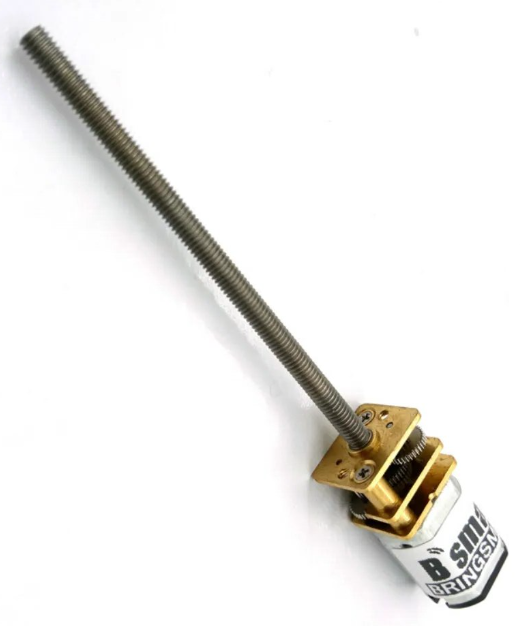
For electronics, I decided early to keep it rather simple and use only components I had lying around. I mean, I was waiting for motors but there was no reason why I couldn’t just cobble something up.
The first decision I almost always like to make is how I will control the darn thing. In this case I saw myself using combination of a rotary button and a small OLED screen.
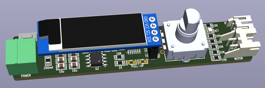
The rotary button I had was the one I used for a few projects in the past, which was Bourns PEC12R, more precisely its PEC12R-4220F-S0024 variant. It’s 12mm square, has detents (which I love), and you can also press it to get button functionality. Essentially, you have left/right/button controls. Ideal for something like this.
The screen I also had decided early on. Small 128x64 I2C OLEDs are easy to obtain and easy to drive. Even better, I had quite a few of different ones laying around from previous projects (e.g., USB OLED).
Input-wise, I wanted to connect it all via just a standard 3.81 mm Phoenix-style MC connector. These are really easy to work with, available from multiple manufacturers, and I have a load of these always in my storage.
For output, I decided to use JST XH connector. Using a different connector here was just to make it really clear what goes where. If I can do it, I always try to do different connectors for each functionality board might have. Makes mistake a lot less likely to happen.
As a trigger for paste dispensing, I decided to use both an on-board button and an external connector. While having a button on board was a handy thing to have during the testing, I really wanted an external connection for a foot pedal. Not only are they easy and cheap to get, but they’re the only practical way to trigger something while keeping both of your hands free. And yes, in order to avoid potential errors, I used a JST PH connector here.
The last selection was a PIC microcontroller. And yes, I knew it would be a PIC since those are the only ones I have in my storage. I did play with some other microcontrollers out there, but my pipeline and knowledge are so heavily skewed toward PIC that I always select it for projects like this. And here I opted for PIC16F1454. While many other Microchip devices would work equally well, I had a load of PIC16F1454 in my storage.
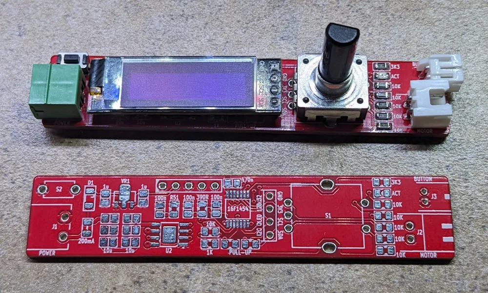
PCBs were made by PCBWay and provided to me for free. While they do sponsor me occasionally, I actually did quite a few orders with them where I paid my own money to get stuff made. They were fast (well, much faster than me doing my part) and boards ended up being exactly what I ordered. Unfortunately, that meant they had a few errors - none of which were PCBWay’s fault.
The first issue I noticed was actually reaching programming ICSP header. OLED simply didn’t leave enough space to reach the darn thing. Fortunately, I use Pogo pins with my PICkit so I could reach the header from the bottom. Had I been using just a standard header, it would have been really a deal breaker.
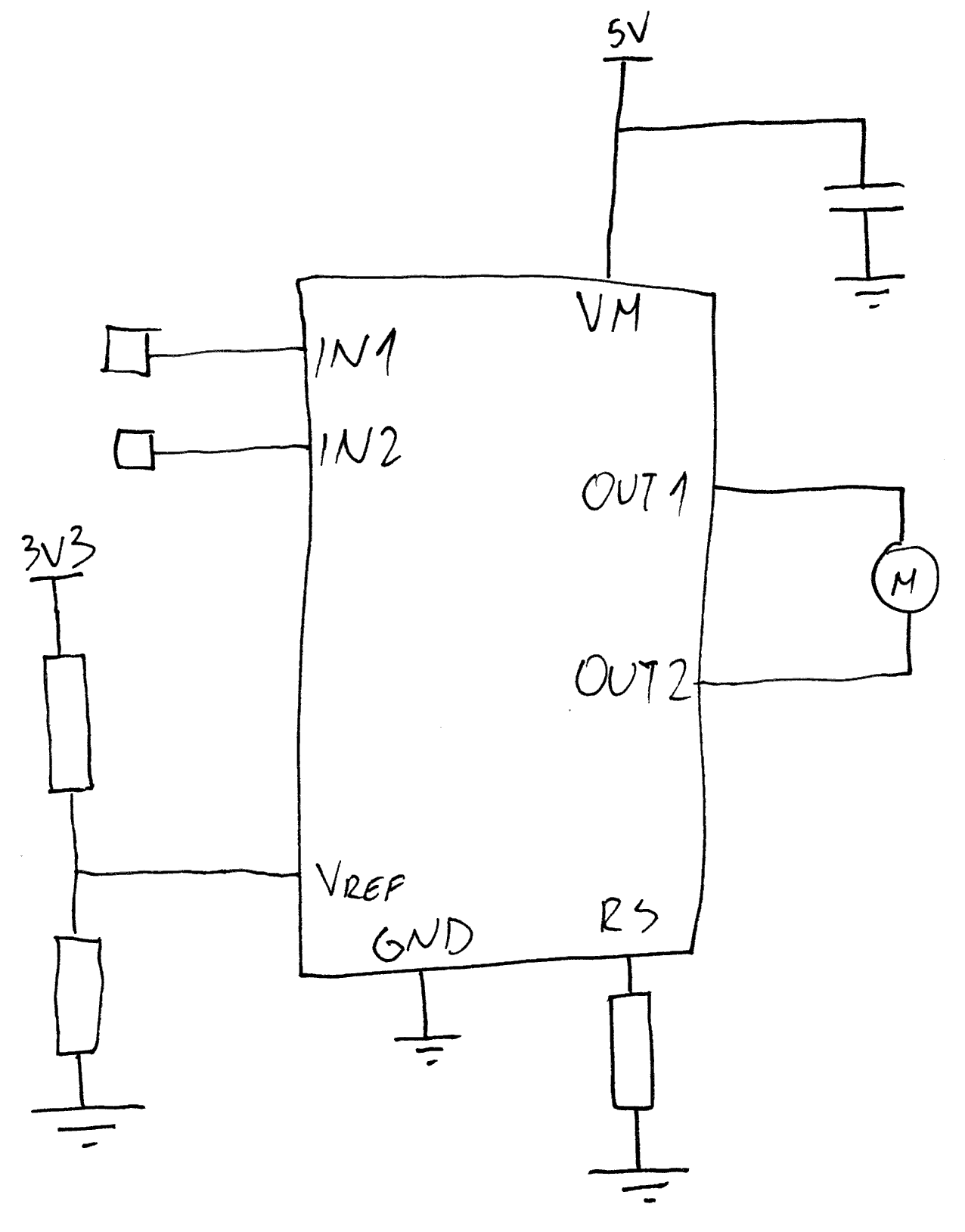
Second, a more serious issue was with the motor driver simply not working. All voltages were just fine when the motor was not connected. However, connect the motor and it would go nowhere. It took me a bit of troubleshooting to notice I messed up Vref voltage divider and that was causing any load to trip the current limit function on my motor driver.
As I already soldered the whole board, I had to unsolder the OLED to reach resistors underneath and place a bodge wire. Since I use lead-free solder, it took a considerable amount of heat to fix that and the board survived that without any issues. The same couldn’t be said for my OLED display which didn’t work after I placed it back. So I had to unsolder it again in order to solder a replacement.
Why I mention this? Well, playing with higher temperature quite often damages the soldermask. And I had that experience with many PCB manufacturers, including PCBWay. However, either PCBWay changed their soldermask formulation to handle the higher temperature or this red soldermask I selected is a bit more resilient as after cleaning it with alcohol, I couldn’t even tell it was ever worked on.
And that’s all for this installment of the project. See you next time when I get the firmware running and see how this works in practice.