Recovering ZFS
Well, after using ZFS for years, it was only a matter of time before I encountered an issue. It all started with me becoming impatient with my Ubuntu 20.04 desktop. The CPU was at 100% and the system was actively writing to disk (courtesy of ffmpeg), but I didn’t want to wait. So, I decided to do a hard reset. What’s the worst that could happen?
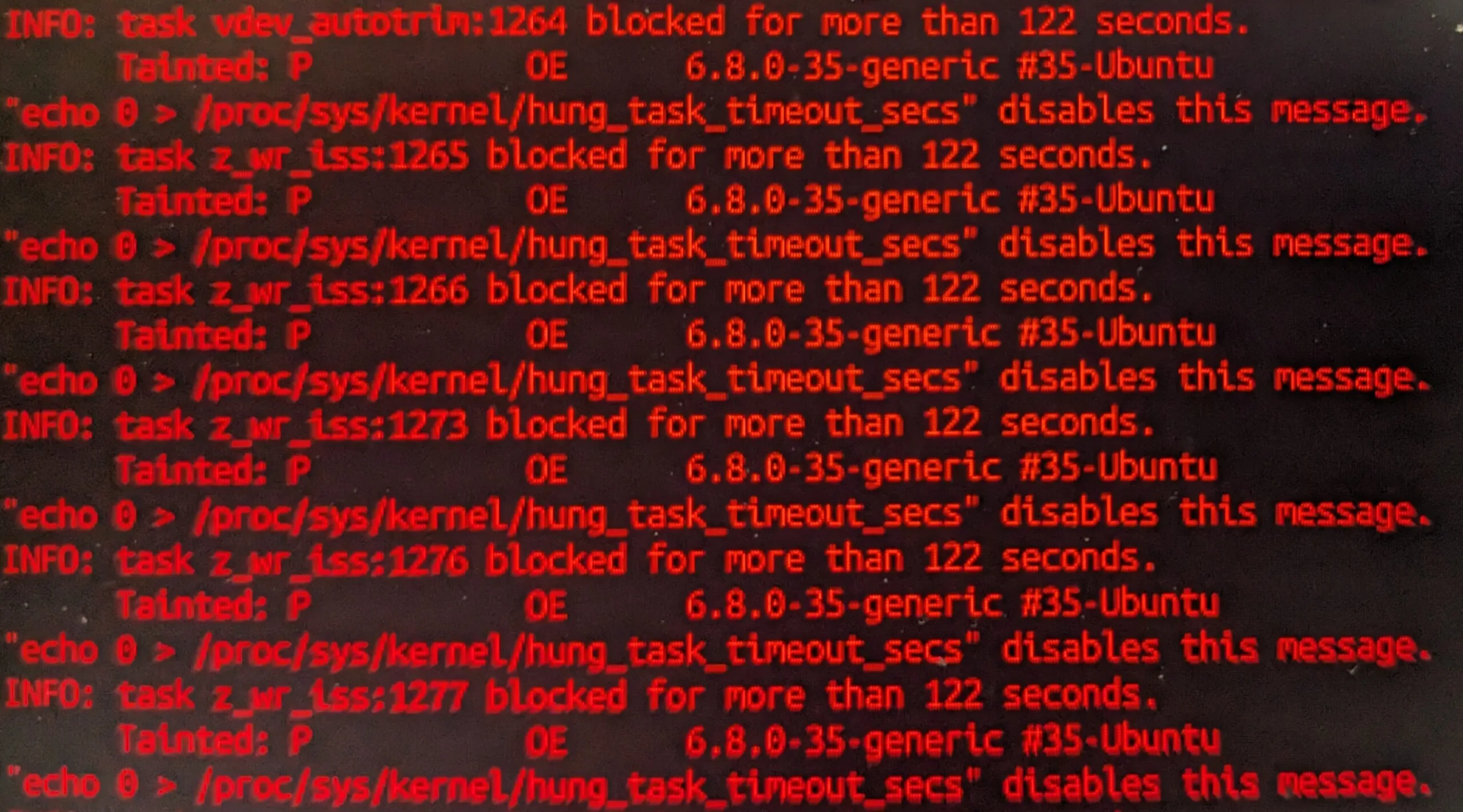
Well, boot process took a while and I was presented with bunch of entries looking like this:
INFO: task z_wr_iss blocked for more than 122 seconds.
      Tainted: P      0E      6.8.0-35-generic #35-Ubuntu
"echo 0 > /proc/sys/kernel/hung_task_timeout_secs" disables this message.
INFO: task z_metaslab blocked for more than 122 seconds.
      Tainted: P      0E      6.8.0-35-generic #35-Ubuntu
"echo 0 > /proc/sys/kernel/hung_task_timeout_secs" disables this message.
INFO: task vdev_autotrim blocked for more than 122 seconds.
      Tainted: P      0E      6.8.0-35-generic #35-Ubuntu
"echo 0 > /proc/sys/kernel/hung_task_timeout_secs" disables this message.
…
At first, I thought the system would recover on its own as this wasn’t the first time I had mistreated it. However, leaving it alone did nothing. So, it was time for recovery.
The first step was getting to the GRUB menu. Pressing <ESC> multiple times during boot simply dropped me to a prompt. And yes, you can load initramfs manually from there, but it’s a bit tedious. However, in this case, I just typed normal to get the menu, followed by <E> to edit the line starting with “linux”. There, I appended break, telling the system to drop me into initramfs prompt so that I could manually load ZFS.
From here, there was another hurdle to bypass. While this stopped before ZFS was loaded, it also stopped before my disks were decrypted. Had I used native ZFS encryption, this wouldn’t be a problem, but I wanted LUKS, so now I had to load them manually. As I had a mirror, I used the following to open both:
DISK1=/dev/disk/by-id/nvme-<disk1>
DISK2=/dev/disk/by-id/nvme-<disk2>

cryptsetup luksOpen $DISK1-part4 ${DISK1##*/}-part4
cryptsetup luksOpen $DISK2-part4 ${DISK2##*/}-part4
Finally, I was ready to import the pool and decided to do it in read-only mode:
zpool import -o readonly=on <pool>And surprisingly, it worked. That also meant that my recovery efforts didn’t need to go too far. So, I decided to try importing it again but in read/write mode:
zpool export <pool>
zpool import <pool>
And then I was greeted with an ominous message:
PANIC: zfs: adding existent segment to range treeHowever, the import didn’t get stuck as such, and my data was still there. So, I decided to give it a good scrub:
zpool scrub <pool>While the scrub didn’t find any errors, going over all data seemed to have resulted in data structures “straightening out” and thus everything looked as good as before.
One reboot later, and I got into my desktop just fine.
PS: If that failed, I would have probably gone with zpool import -F <pool>.
PPS: If that also failed, disabling replays would be my next move.
echo 1 > /sys/module/zfs/parameters/zil_replay_disable
echo 1 > /sys/module/zfs/parameters/zfs_recover
PPPS: You can also add those parameters to “linux” grub line (zfs.zil_replay_disable=1 zfs.zfs_recovery=1).