After a long wait, Visual Studio 2017 is here.
Even better, if you download it until March 14 (π), you will get 60 days of Xamarin Univerity for free. But wait, that is not all - if you react now, there is a knife set just waiting… :)
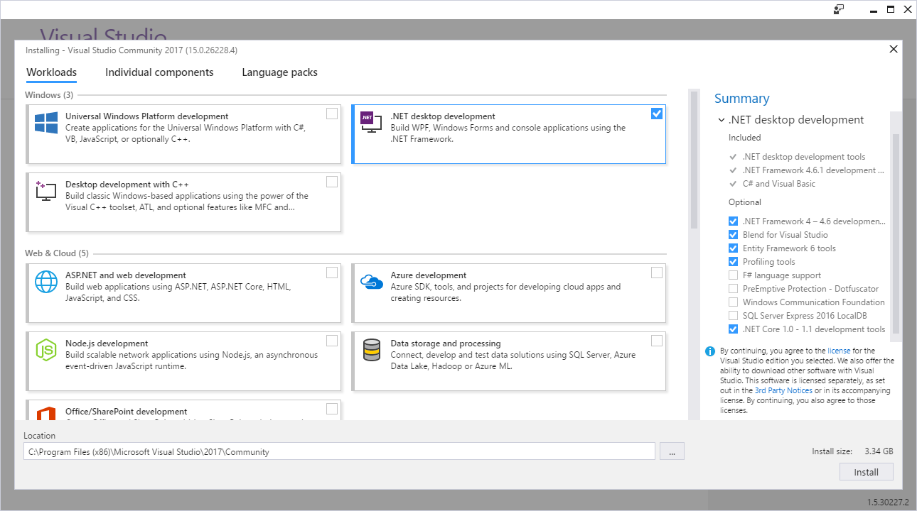
First thing you will notice is a new installer. Yes, you could already see it during RC phase, but this one got a bit more options and new, a bit uglier :), interface. You might be temporarily scared a bit when you notice there are no ISO files to download. Fear not - you can still make an offline installer yourself. However, do notice that downloading everything will be around 24 GB (77 GB when installed). You might want to consider limiting yourself to just the workloads you need.
Full list of features you can find in release notes but I can already guess that most of people are interested into C# 7. My personal favorite is actually possibility to declare out variables in-line. Yes, I know that out variables should be used sparingly as quite often people get puzzled by them. However when you do lot of parsing, out variables can actually be the cleanest way to get something out without introducing helper class explosion. Other features in C# 7, local functions, is expressions, value tuples, ref returns…, are following the same line of simplifying the code without introducing extra fluff.
Additionally .NET Core finally got integrated properly into Visual Studio. I am all ok with doing ghetto project creation but there is something to be said about getting the big guns out when necessary. Debugging comfort simply does not compare between the two in my opinion.
Of course, there are some already known issues but I found nothing of real significance. I admit not being to clone SSH repository does sound damning but realistically most of time you are going to do that from command line and not from Visual studio so that doesn’t really count :P. Also, don’t forget to install .NET Framework 3.5 development tools if you have any legacy .NET 2.0 applications - otherwise they will be marked as 4.0.
I personally already moved to Visual Studio 2017 Community Edition but that might have not been a huge step as I dabbled in Release Candidate too. As for you, what are you waiting?
PS: Unfortunately Express editions are still not available but there is a positive confirmation they are coming really soon.
PPS: Xamarin University offer is actually not that impressive - it is pretty much useless as anything interesting requires subscription upgrade.
[2017-09-15: Express 2017 for Windows Desktop (preview) is available!]
[2017-10-16: Express 2017 for Windows Desktop is here - albeit for the last time.]