Post series about creation of AuxPower1U device

AuxPower1U: Mistakes were made

This is a post 11 in the series (previous: Main Controller PCB).


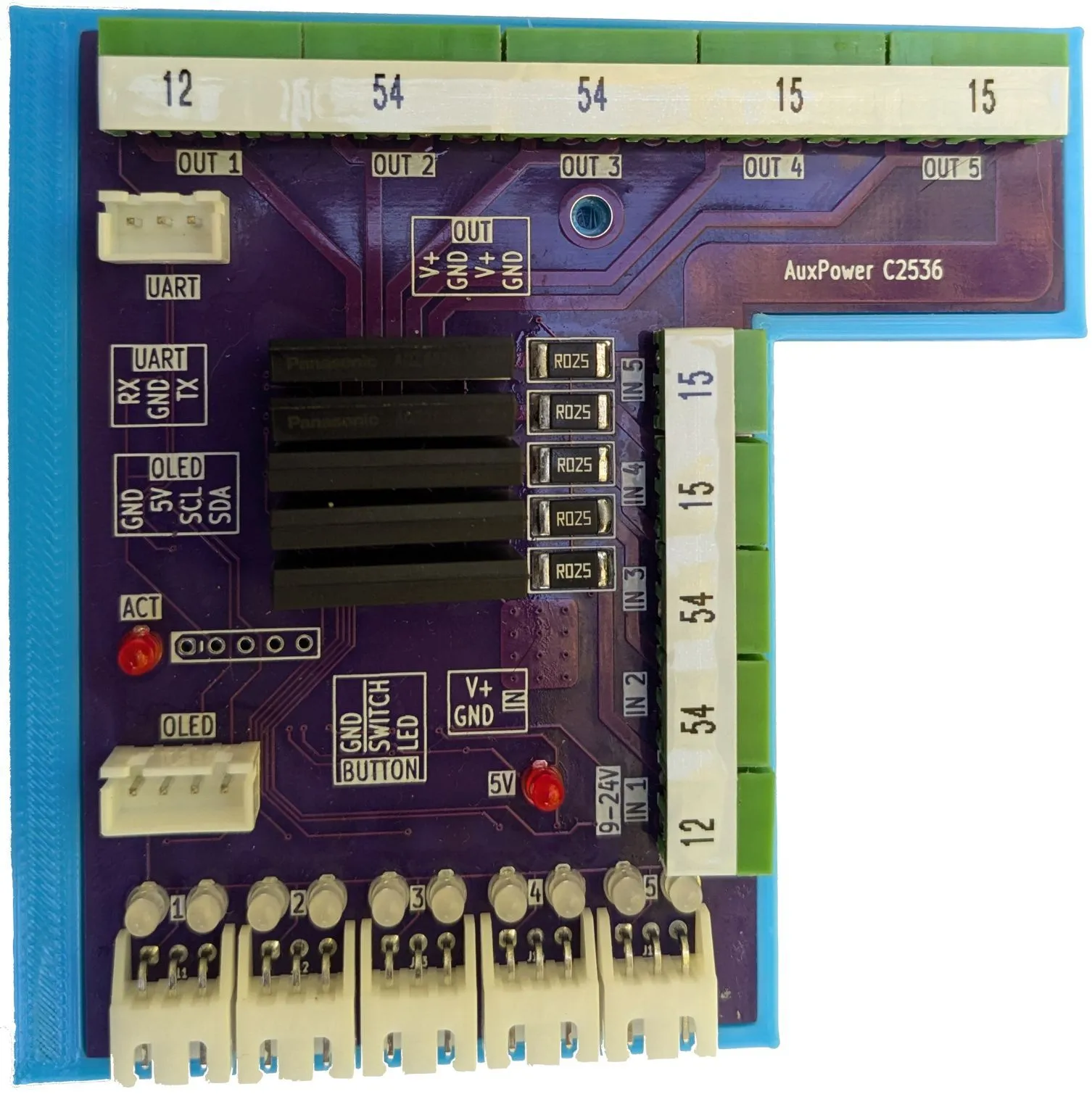
With AuxPower1U being an actual physical object, I can see there were some mistakes. Most of them I worked around for and they’re already fixed in the repository for potential future version. But some of them will remain as a design choice.

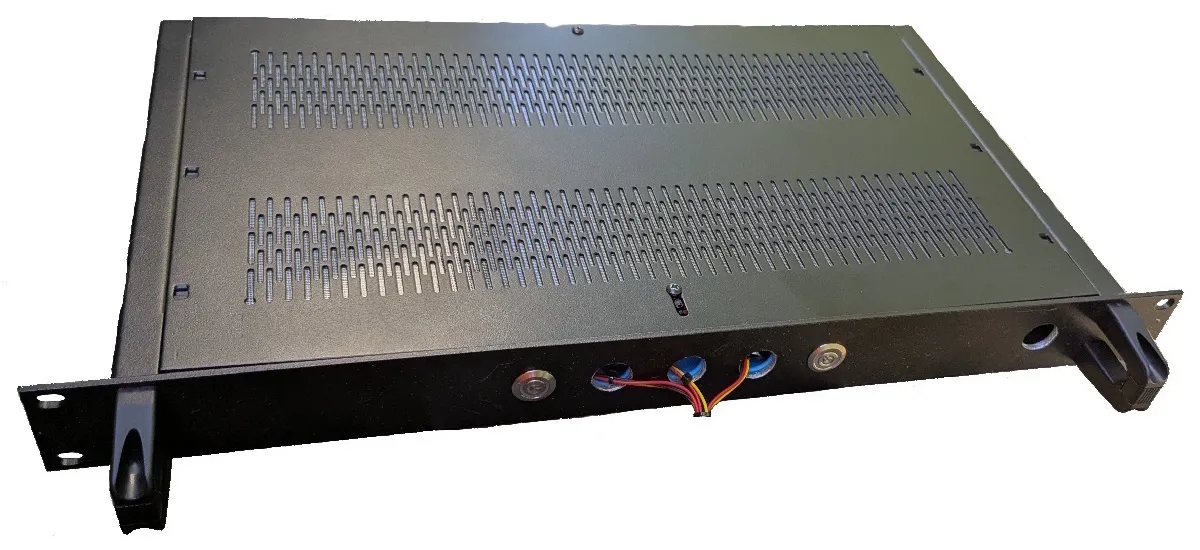
First one has nothing to do with electronics but with my aluminium plate (aka “heat sink”). I planned for tapping holes so I can screw power supplies directly. Unfortunately, my model actually swapped diameter and radius and thus I got holes much bigger than I wanted. Classic error. So I used just screws and washers to get over that. But that actually made me think - do I really want to make all those tapping holes? Answer is no - longer screw and nut are good enough.

With that out of way, next portion are the PCB errors that were fixed courtesy of PCBWay respinning my desing. While the first revision board could be fixed using bodge wires, and I did so for firmware development, errors were big enough that I really needed a new PCB.

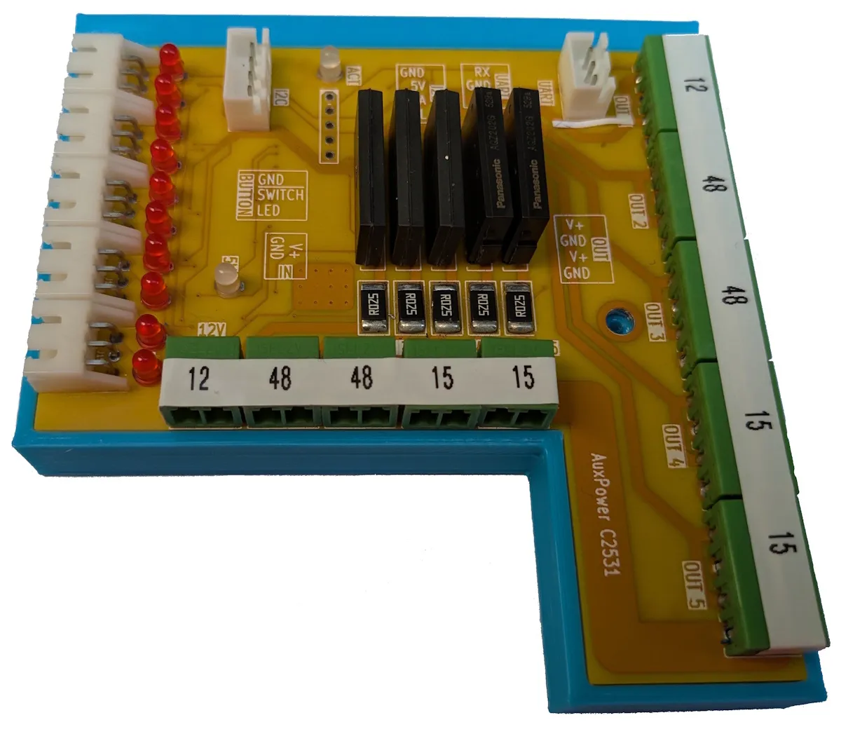
Current monitoring was the bigest miss here. I used my trusty ZXCT1009 - something I used many times ago. So, of course, I forgot to include ground resistor which made its readings go wild. Connecting resistor via bodge wire fixed that error. But, only when testing at 30V released the magic smoke, I checked the data sheet more closely. Yes, ZXCT1009 is limited to 20V. This never came up as most of my designs stick to 12V at most. But it became problem now.

However, finding a chip that goes up to 60V proved to be a difficult task. There actually are not too many simple chips that go that high and I didn’t want something that has more than 3 pins. Well, I think I found my new favorite current monitor - HV7801.

While HV7801 has more than 3 pins, it still comes in SOT-23 package and requires no external components. It actually occupies less PCB realestate than ZXCT1009. Downside is that its gain is fixed to 5x thus requiring me to use 1.024V ADC range. With ZXCT1009 it’s much easier to get resistor dividers than are nicely “rounded” for ADC and fit almost any range. With HV7801 you get what you get. Despite all of this, if I need current measurement that doesn’t need to be precise and I have 12-bit ADC, this chip is awesome.

Speaking of current measurement, I used 0.1Ω 3W resistor at first. It’s the same resistor I used in many other projects and it was always an overkill. What I temporarily forgot is that my low voltage ranges (e.g., 15V) will need to pass a lot of current. Thus, my trusty 0.1Ω resistor was getting way more heat than appropriate. After actually running the numbers, I decided to go with 0.025Ω 3W. Still gives nice figures for microcontroller calculations while producing way less heat.

Unfortunately, since my MCP9701A temperature sensor outputs around 800 mA at the room temperature, usage of HV7801 also meant I have to switch ADC ranges every time I measure the current. MCP9701A at 1.024V ADC range would only allow measurement up to 32°C. Even its 9700A brother (that I didn’t have in stock) would only allow up to 62°C. Switching to 2.048V just for temperature measurement is not the end of the world but it does mean slower measurement and it probably has implications for precision too.

One other case of “the forgotten resistor” is a pull-up for output MOSFETs. Early in the design phase I decided that resetting the board should not bring outputs down. Idea behind it is that, even if my board misbehaves, current will flow. There are merits on starting the system with all devices off but, since this would control power to my wireless, I decided it should fail-closed. And for that you need pull-ups. That I have forgotten.

Since we’re talking about resistors, I also had to increased ones used for LEDs. Those things were just too bright. While this means absolutely nothing once box it closed, it meant a lot during debugging since I could actually look at the PCB without burning my retinas. See, high-efficiency LEDs are not always good. :)

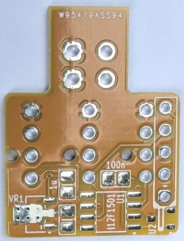
Speaking of debugging, I originally had my ICSP (i.e., debugging) lines shared with UART. This was necessary as I didn’t have enough pins and had to make some share functionality. Later in the project I added an I²C extender and thus aleviated the issue. However, I forgot to decouple UART lines from ICSP thus making the debugging of UART communication impossible. Solution was simple enough - just move those lines.

With all these errors, you can see why revision B was needed. While many of errors could be sorted by bodging wire here and there, and indeed they were for the purpose of firmware development, it was just too many to ever trust that board. Revision B saved the day.

AuxFanControler, a New Revision

As part of my AuxPower1U project, I already build a stand-alone 4-channel fan controller. And it works perfectly even now. But I did notice some issues when trying to use it as part of other projects.

The first issue was it belonging to AuxPower1U Git repository. There was nothing wrong with that but, since I used it for other projects too, it seemed right for it to get own repo. And its own repo it got. While I will keep it compatible with AuxPower1U, each can change separately.

The second issue was its dimensions. Even though I would argue you cannot get 4-channel fan controller with those connectors in much less space, reality was that vertical mounting was impossible in 1U chassis. Not only that its sideway power entry made wire routing particularly bad in vertical scenarios but it also meant that total height was cutting it close for even 2U case. Reducing the PCB height was an obvious choice and while trying to figure out the layout, I decided to drop one fan connector. This allowed me to reduce size from 69x15mm to more reasonable 42x15mm. Just barely fitting 1U if we ignore sideway cable entry. And ignore it we can because I also adjusted connector to allow for mounting either vertical or horizontal connector. Yes, you will have one footprint unpopulated but that’s a small price to pay.

A third, minor issue was that board was hard to mount. For this I intentionally left back front side empty and with a bit wider side margins. This allows one to create slot in plastic and thus keep the board embedded with friction alone or, if needed, with just a touch of plastic. How that mounting looks like you can see on example of the new AuxPower1U board (that I’ll cover a bit later due to scheduling carfufle). Board sits between 2 fans and goes nowhere once slotted in.

Illustration

I got PCBs from PCBWay and it arrived quite quickly. More importantly, its edges arrived cleanly cut. This is not something one notices unless they deal with some other PCB providers. I love OSHPark but them leaving tabs in place drives me crazy. Every time I get their boards, I have to spend minute or so per board filing those tabs down and it’s never fully straight edge. With PCBWay at least that task is of my back.

Also, compared to OSHPark they have way wider color selection. You can chose green, red, yellow, blue, white, or black for the same price. This allows you to distinguish boards at a glance. For this order I opted for the yellow soldermask which is not my favorite when it comes to reading slikscreen but it is rather nice otherwise. If silkscreen legibility is at premium, either red or blue are better choice. But that is the beauty of choice. You can find what works for you in any particular scenario.

Premium colors like purple, matte black, and matte green do come at a greate cost. However, they do ocassionally get a discount so its worth checking them out from time to time. For example, purple is going to be available at standard $5 price in September so you might want to check it out. Speaking of discounts, 3D printed TPU will be heavily discounted in September too so you might want to check it out. As somebody who printed TPU, I can only recommend you get somebody else to do it. :)

Illustration

Soldering this PCB was a bit more difficult as compared to the revision A because components were a bit more pushed together. But that’s just relatively speaking - I am still using rather generous pad size so it should be easily doable.

Profile is similar to before but with a bit more agressive curve between 60-70 °C. This is something I plan to make configurable eventually but I don’t really have reason to do so right now.

Startup sequence is still powering fan at a time with a quick spin-up to 100% before settling down. Firmware itself still behaves as if it has 4 channels which makes firmware the same between revision A and B.

It’s just a small update but form factor change alone will allow me to use it in way more places that require stand-alone fan control.

New case for AuxPower1U

My AuxPower1U project was over and all was great. But, one thing always annoyed me - the plastic enclosure. Don’t get me wrong, it is a nice enough enclosure when mounted. But, since power supplies do weight a lot, chasis flexes if unsupported. Not a big issue but not something I like. So, when I ran into a Cheval PF19AL1UD1, I immediately started eyeing an upgrade.

Illustration

It is a 1U case, a slightly longer than Bud PRM-14460 - 200 vs 240mm. It has ventilated sides in addition to vented top and bottom plate. And it features internal box design with rack mounting being a separate element. While this might be excellent for some projects, I had a few issues with it.

The first issue was it’s box construction with rack mounting being a separate element. Since I needed to drill the front, this was annoyance. Thus I decided to simply omit front extrusion when mounting it. That way I only needed to drill one set of the front holes. As this change made top and bottom flimsy, I had to redesign aluminium plate mounting to stiffen it a bit. Once buttons are mounted, there should be no play.

Another issue I had was with vented top and bottom. While usually a great feature, they were killing my air flow setup. At the end, I just covered them from the inside with a wide duct tape so that air is forced over power supplies.

As luck would have it, all mounting solutions I did for the previous case would not fit this one. Aluminium plate couldn’t rely on central bosses because there were none. Also mounting controller and fans had to change too because there is now no real place to screw it. Mind you, mounting options are probably even better now - there are enough M3 holes available.

In the end, it took a few hours of reacquainting oneself with FreeCAD to get everything in place. And I believe it was worth it. Metal case just feels much better than the plastic one it does offer way more space because there are no protrusions in the middle the plastic case needs.

That said, it is more compliated to work with than the plastic. First of all, drilling is much more work. And, since there will be live AC power in it, grounding case properly is a concern. With powder coated case this means a lot of scraping to expose metal. Nothing too difficult but important not to forget.

But drilling and grounding is a problem for the future me.

The New Controller

Illustration

With the new case sorted out, I decided onto a new power supply controller. Since I recently ended in the possesion of a few PhotoMOS device, I figured to check them out. While my own high-voltage MOSFET switching does work, there is no real isolation between my control circuit and the output voltage. PhotoMOS brings that additional safety.

Changing to AQZ202G PhotoMOS required a major PCB redesign. Fortunately, controlling PhotoMOS was trivial and thus most of time was just figuring how to lay things out without changing PCB size. After hours of “playtime” in KiCad, I sent the new PCB toward PCBWay to manufacture.

Once I got my boards back, I decided to first test it with a cheaper CPC1706Y PhotoMOS. I though yhe only difference between Littelfuse and Panasonic ones was the maximum current. Panasonic supported 6A (which I needed for my 65W PC connectivity) while Littelfuse PhotoMOS supported 4A. Since my fist three power channels were low wattage, I opted to use CPC1706Y for them, reserving AQZ202G for the channel 4 and 5.

And all channels worked flawlessly. Heck, channels CPC1706Y worked even when they were supposed to be off. At first I though it was due to firmware changes I did. But, an embarassing amount of troubleshooting later, I noticed that there is one more difference between Panasonic and Littelfuse. Panasonic uses bidirectional MOSFET switch. Littelfuse does not.

That means that Panasonic doesn’t really care which connection is more positive. And, since I used Panasonic to create KiCAD footprint, I opted for easier routing. But Littelfuse cared which connection is more positive and I selected wrong. Well, after another hour or two of moving traces around I was ready for another go.

Illustration

Since PCBWay has an action going on where you could get a purple PCB for no extra change, I decided to try it out. And, while coloring PCB is a gimmick without impact to electrical design, over time I grown to appreciate it. With PCBWay offering multiple colors, I always alternate them between orders allowing for easier distinguishing between revisions. It’s way easier to tell whether PCB is purple or yellow at a glance, than if revision is C2531 or C2536.

Combinination of purple PCB and white silkscreen is a really a classical one in a hobbyist circles and PCBWay doesn’t disappoint here. While it is slightly lighter shade of purple than OSHPark, solder mask is of equally same high quality. It handled my clumsy soldering like a champ. :)

All in all I am mostly happy with the new PhotoMOS solution. As compared to my MOSFET switching it offers way better isolation from the rest of my circuit. Heat is about the same which is not surprising. However, when it comes to cost, there is really no competition. Darn PhotoMOS devices are EXPENSIVE. If price is a major consideration, it’s a no-brainer to roll-your-own.

For my AuxPower1U controller, I think I am going to stick with PhotoMOS. They do offer isolation and they are much easier to control. And, since this project is not cheap due to quite expensive power supplies, increase in cost is bearable.

The New Firmware

Illustration

With all the changes in the AuxPower1U project, it was inevitable that firmware will change too. However, some changes were in order.

First was in regards to my PhotoMOS setup. While 6A AQZ202G PhotoMOS supports all I need, I only had 2 of them handy (actually, I started with 3, but we won’t discuss my testing procedures). So, I filled rest of channels with 4A CPC1706Y PhotoMOS. Why am I mentioning hardware in the firmware part? Well, part of my firmware is handling safety cutoffs. And those are not the same between all channels now. Yes, these are still hard-coded because I am too lazy to create GUI. But they are separated into a function so changing them shouldn’t be a chore. The first three channels have 4A safety limit while the last two have full 6A.

Another change was turning off display after a period of inactivity. While having it always visible was handy, it did cause degradation in cheap displays. After months of having it on with the previous display, burn-in was becoming a problem. Since I rarely check that display, it seemed like a good idea to simply turn it off until button press is detected. Cheap firmware solution for a hardware problem.

And lastly, I changed how output pins are handled. Originally, I handled them via I2C expansion which works like a charm. But, that introduces an extra device in what you might call a critical path. Since, due to other changes, I did have 5 pins available, in the new revision output is controlled directly from microcontroller without going to the expander board. As to preserve compatibility with the previous board, code sets both I2C and pins directly. That way both revisions can work on the same firware.

With all this, my AuxPower1U revision C was ready for “production”.