Having OpenVPN server on your router is a nifty feature. However, as often with Mirotik, not all is straight forward.
This guide is going to assume you are to enter commands into the New Terminal window from WinBox. That way I will simply repeat commands needed instead of going through the screens. Commands are actually quite descriptive and easy to “translate” into GUI actions if that is your preference.
Prerequisite for any VPN server is to get certificates sorted. For OpenVPN we need main Certificate Authority, server, and client certificate. Yes, strictly speaking, client certificate is optional but let’s not skimp on security.
First we create all the certificate templates (10 years validity) we’ll need:
/certificate
add name=ca-template common-name=^^example.com^^ days-valid=3650 key-size=2048 key-usage=crl-sign,key-cert-sign
add name=server-template common-name=^^*.example.com^^ days-valid=3650 key-size=2048 key-usage=digital-signature,key-encipherment,tls-server
add name=client-template common-name=^^client.example.com^^ days-valid=3650 key-size=2048 key-usage=tls-client
For the purpose of OpenVPN server common name can be really anything. However, some other VPNs are not as forgiving (yes SSTP, I am looking at you) so it might be best to have either your external IP or host name as the common-name text. Any yes, if you have dynamic IP and you are not using your own domain, you can put *.dyndns.org there - no worries.
Created certificates will need signing:
/certificate
sign ca-template name=ca-certificate
sign server-template name=server-certificate ca=ca-certificate
sign client-template name=client-certificate ca=ca-certificate
Depending on your router’s speed, that sign command might time-out - nothing to worry about - just wait for CPU to drop below 100%. Or alternatively check name of certificate - template part will disappear once signing is completed.
With this we need to export a few files:
/certificate
export-certificate ca-certificate export-passphrase=""
export-certificate client-certificate export-passphrase=^^12345678^^
This should give you three files: cert_export_ca-certificate.crt, cert_export_client-certificate.crt, and cert_export_client-certificate.key. After copying this on computer for later I like to rename them to ca.crt, client.crt, and client.key respectively.
Next we need a separate pool of IP addresses for clients. I will assume you have your clients in some other network (e.g. 192.168.1.x) and this new network is just for VPN:
/ip
pool add name="vpn-pool" ranges=192.168.8.10-192.168.8.99
Instead of editing the default encrypted profile, we can create a new one. Assumption is your Mikrotik will also be a DNS server. And while at it, you can create a bit more imaginative user/password:
/ppp
profile add name="vpn-profile" use-encryption=yes local-address=192.168.8.250 dns-server=192.168.8.250 remote-address=vpn-pool
secret add name=^^user^^ profile=vpn-profile password=^^password^^
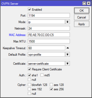
Finally, we can enable OpenVPN server interface:
/interface ovpn-server server
set default-profile=vpn-profile certificate=server-certificate require-client-certificate=yes auth=sha1 cipher=aes128,aes192,aes256 enabled=yes
Now finally we can copy both ca.crt and client.crt to C:\Program Files\OpenVPN\config\ directory alongside client.ovpn.
You don’t have client.ovpn? Well, one is in sample-config directory and we just need to change/add highlighted items:
client
dev tun
proto ^^tcp^^
remote ^^example.com^^ 1194
resolv-retry infinite
nobind
persist-key
persist-tun
ca ca.crt
cert client.crt
key client.key
remote-cert-tls server
cipher AES-128-CBC
^^auth SHA1^^
^^auth-user-pass^^
^^redirect-gateway def1^^
verb 3
A bit annoying step is being asked for the private key passphrase (in the addition to username/password). Mikrotik doesn’t allow export without it but fortunately we can use OpenSSL to change that:
openssl.exe rsa -in client.key -out client.key
 Enter pass phrase for client.key: 12345678
 writing RSA key
With this, your VPN connection should work like a charm.
PS: Do not forget to adjust firewall if necessary (TCP port 1194).
/ip firewall filter
add chain=input protocol=tcp dst-port=1194 action=accept place-before=0 comment="Allow OpenVPN"
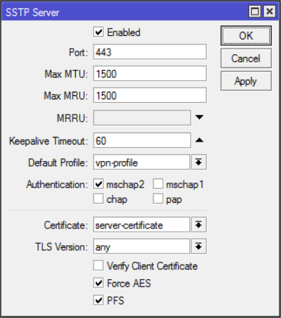
PPS: Do check SSTP guide too.
PPPS: If you’re on RouterOS 7 you might want to check this guide for UDP.
[2017-01-26: Adjusted certificate creation to work on RouterOS 6.38 and later] [2017-01-26: Changed key size to 2048 (instead of 4096) so it doesn’t take ages to generate certificates. :)] [2017-02-25: Changed example to use AES-128 for lower CPU usage on router.]