 I have designed a few framework expansion cards already, but I tried to keep them data-only interface. That is, I avoided providing power as much as possible. And, in my opinion, that's the proper way of doing it. However, what if I occasionally want to provide some power too? Can it be done (reasonably) safely?
Considering my intentions of using an expansion card, and thus sourcing power directly from the laptop, my goals were to avoid the two most common issues: current backflow and current limiting.
While using fuses for current limiting is a traditionally accepted method, it's neither precise nor fast enough to protect a laptop. Fortunately, there are load switches that allow for not only precise current limiting but also for fast response.
My choice fell onto AP22652Wx family. These devices allow for quite precise current limiting using external resistor, short-circuit and reverse voltage/current blocking. All that in a small SOT26 (aka SOT23-6) package.
As it often goes, we do need a few external components too - at least one resistor (to limit current) and at least 100 nF decoupling capacitor. Realistically, if you're not sure what gets connected on the other side, you need a few more capacitors. I usually opt for 100 nF/10 μF combo on both input and output. And here is the biggest disadvantage of using load switch - quite a lot of PCB real estate.
Second issue I mentioned (current "backflow") is also known as reverse current. This happens when one accidentally connect a positive voltage to a power output. As often in life, bigger force "wins" and thus current will start flowing into the output pin. When that device is a framework expansion card powered by laptop
itself, this is definitely not the most comfortable situation.
Load switch I selected does offer basic reverse-current protection, but I wanted a bit of a foolproof solution and that comes in the form of a humble diode. Such forward biased diode will allow current to flow towards output but it will stop conducting if output voltage goes higher than that. And yes, that comes at a cost of voltage drop. However, if you keep current low, voltage drop is still within a few hundred millivolts.
In my case I decided to limit current to 400 mA and thus CUS08F30 I selected has not only healthy headroom with current but it would drop under 400 mV at a full load. Yes, there are diodes that have even better characteristics but this one comes in quite a small package and I already had it lying around.
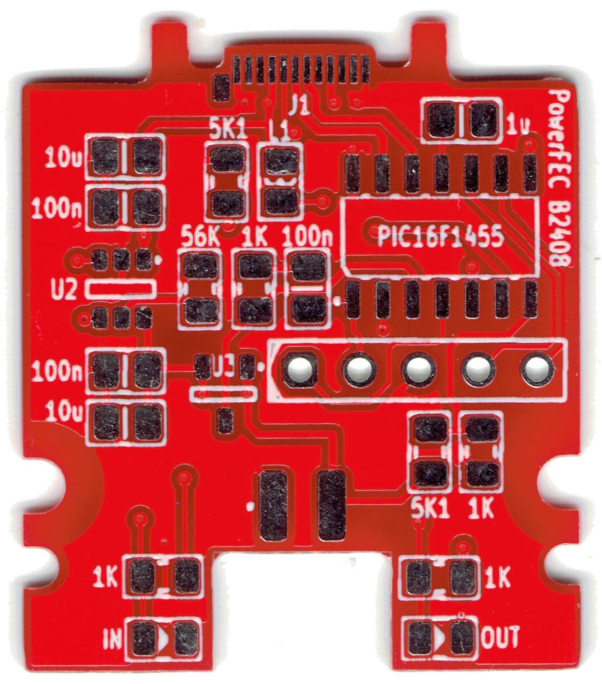
With theory solved, it was time to test it. For that purpose I've created a new Power framework expansion card https://github.com/medo64/PowerFEC. I used PIC16F1454 to interface it to USB, small ZXCT1009 to measure current, in addition to load switch and diode described above.
PCBs were manufactured courtesy of PCBWay. When it comes to framework expansion cards, they became my go-to manufacturer for two reasons. The first one is their standard routing bit seems to be much smaller than the one used by competition. This is important when it comes to the Type-C edge connector which requires a really small feature that large routing bits will mangle. The second nice thing is that PCBWay doesn't use break-away connections, opting instead for V-groove. This means the edge is as perfect as it gets, saving me from manual sanding.
And yes, they're not perfect. They still put their screen markings (you can pay extra to keep it clean). They still use leaded HASL (you can pay extra for non-leaded or ENIG). And sometimes waiting for somebody to manually check PCBs really clashes with my habit of finishing PCBs just before my bedtime thus forcing me to wait (albeit never too long).
But, all in all, those are all things that are minor enough not to bother me too much. I haven't had bad PCBs from them in ages. Quite often with small PCBs I would get a few more than I ordered. And HASL is fine for pretty much all my use cases. While this PCB was sponsored, I used PCBWay on my own dime without complaint.
In order to make it all work, I decided to reuse my old code and make device behave as a serial port. It will output voltage and current in addition to allowing for a few basic commands (e.g. enable and disable).
After messing with it quite a while, I found protection working pretty much perfectly, thus expect a few updated expansion card designs in store.
As always, hardware and software are available on GitHub