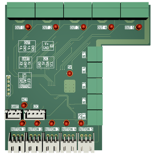
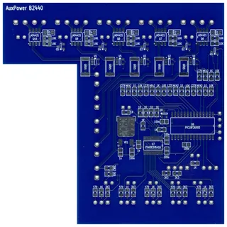
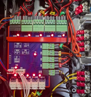
AuxPower1U: Main Controller PCB
This is a post 10 in the series (previous: Switching the High Voltage).
Well, after many posts about my AuxPower1U project, it came time to show the star - the main controller board. Its function is to pass voltage from input to output, interrupting it when necessary.
Due to cost and limited space for actual mounting, I first defined the size. Since I wanted to use Phoenix MC connectors, the width had to be 90mm in order to accommodate 5 4-pin outputs. Since I will be mounting power supplies on its right side, all 5 2-pin inputs will go there. On the bottom, I have 5 3-pin connectors for a switch and its LEDs, so the height ended up being 90mm too. And yes, that’s under 100x100 mm limit that stays within PCBWay’s $5 offering.
That said, mounting the board, which is 90x90 mm, would be problematic since it almost touches my power supplies. To avoid having everything too crowded, there is a 30 mm deep cutout allowing for much easier plugging and unplugging. And yes, that did make routing slightly more complicated thus requiring slightly narrower traces than I would usually prefer.
Upload to PCBWay was as easy as always and I probably had my order ready in 10 minutes. Manufacturing was a bit slower for blue PCB I decided to get, so you mgiht want to go with green soldermask if speed is of essence.
PCBs that arrived from PCBWay were as good as always. I opted for a standard HASL surface since I didn’t use any troublesome components. The smallest pitch on my board was 0.5 mm and PCBWay’s HASL is more than sufficient for this. There was an option to go with 2oz on the the board but I opted to use wider traces instead. Yes, a 2oz pour is better for temperature, but it does bring the price signigicantly up.
PCBWay offers FR-4 at their baseline PCB material and, during my testing, I went over 100°C for multiple hours with multiple cool-down cycles. There was no sign of delamination and thus I am fairly comfortable this PCB will handle all the power I need without any issue, especially since there will be fan cooling it down. Furthermore, since I do measure current, firmware can easily cut off power if things go crazy.
All connectors and status LEDs are on the top of the PCB, with the actual chips delegated to the bottom. I believe this gives it a better look overall and greatly reduces the chance of me accidentally knocking a component off udring installation. As you can see, this whole thing sits in a PCB case with a brace holding it down. What you don’t see are the holes underneeth, alowing for air to pass.
On top, there are also UART and I2C connectors. The UART connector goes into a 2.5mm audio jack, allowing me to both connect and control the device via computer. The I2C connector goes to an OLED display, which provides a bit more feedback than just buttons on its older sibling ResetBox had. Both are really optional for the functioning of the device but they’re a nice addition to have.
On the electronics side, everything is driven by a PIC18F26K83. I had a few leftover from the previous project so I decided to use it despite not having sufficient pin count for what I wanted. I wanted to measure voltage and current (5 pins each), react on buttons (5 pins), control button LEDs (5 pins), control the output (5 pins), use UART (2 pins), I2C (2 pins), and a few auxiliary functions (e.g., temperature). Add ICSP, and it’s clear that the PIC doesn’t have enough pins. But an IO expander does.
So, PI4IOE5V6416LEX got the duty of controlling output, buttons, and LEDs, while ADC measurement and communication were left to PIC. The only loss of functionality was LED dimming, which I used to indicate different states before. However, I can still do blinking, and having an OLED actually alleviated the need for dimming greatly.
One downside is that, if I2C communication goes down, so does my capability of turning outputs on and off. With a benefit of hindsight, I should have probably kept the outputs on the PIC - I even had exactly 5 pins extra available. But that thought only occurred to me after I both designed the board and wrote the majority of the firmware. Since testing didn’t show any issues with I2C despite my best efforts to break it, I will keep that change for potential revision C.
Revision C? That implies that my current board is revision B, and thus it follows that something bad happened to revision A. Well, story of mistakes will follow in the next blog post.


