Type-C Power Delivery as Passive PoE Source - Fixes
This is part 2 out of 3 in the series. PCBs were sponsored by PCBWay.
The first version of any project is rarely without faults. And this one is not an exception.
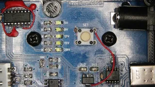
The simplest issue has been me simply forgetting to wire up enable lines on 74HC238D decoder. I assumed, for no good reason, that lines were enabled by default. Thus, no matter what my code did, LEDs stayed dark. After a bit of probing and seeing correct voltage on input, I decided to check the datasheet again and saw the issue almost immediately. A fix required two wires though, as G2A and G2B lines required pull-down while pull-up was required for G1.
The next issue I noticed was that my internal button wouldn’t work. I knew of this risk since, due to pin shortage on PIC12F1501, I ended up using this pin as both input and output. As the microcontroller was booting, I wanted to detect button presses so I can put it into configuration mode. If the button wasn’t pressed during configuration, I would simply use the same pin as power-on signal input towards the transistor. Well, in theory, that should have worked. In practice, I had it pull to ground via an external base resistor. In order to keep the transistor at a known level when the line is input, I used my bodge powers to make the button pull the line high when pressed. Here is where my habit of connecting only two legs of the four-legged button actually helped as I was able to simply snip off one leg and solder 3V3 to another.
With the configuration mode sorted out, I started switching voltages only to find out that I am maxing at 9 V. I could select 5 V just fine but no matter what higher voltage I selected, CH224K would give me 9 V. It took me a while and a lot of datasheet deciphering (Chinese-only datasheet didn’t help) to understand what was happening.
You see, there are two ways you can configure CH224K. You can either use 3 CFG lines to set the desired input state in binary or you can use a resistor on CFG1 line alone. My 10K series resistor made the chip think I was using a single-resistor setting. 10K was close enough to 6.8K so that’s where 9 V came from. In 5 V mode, I had that pin pulled high, and that was enough to stop the single-resistor setup. The solution was to remove series resistors altogether. Ironically, I didn’t actually need them but decided to place them anyhow to help with troubleshooting.
One thing that definitely did help with this troubleshooting was the quality of the PCB. For example, while trying to troubleshoot my voltage settings, I soldered and resoldered CH221K multiple times. Since ground is on the pad that is inaccessible to a soldering iron, I had to reheat the board multiple times. I honestly expected to damage the solder mask after the second time getting it to 300 °C. And while the smell wasn’t the best, the PCB handled it without problems. Yes, you can damage the solder mask if you really want to but it will take a lot more than heavy-handed rework to do so.
With bodges sorted out, the next step will be to update the firmware.
