RS-232 Framework Expansion Card
Boards for this project were sponsored by PCBWay (affiliate link).
A while ago I created a CAN-bus expansion card for Framework laptop. However, I consider this an utter failure. While the card did work, the lack of CAN-bus capable parts meant you cannot actually create one yourself. At least until this IC shortage comes to an end. However, experience was fun enough that I decided to make something else I do need and that one could actually manufacture in today’s world - a RS-232 expansion card.
For those uninitiated, RS-232 is an overall standard that defined connection between different devices for a long time. As many standards go, RS-232 is quite an expansive beast with many different signals. However, over the time, it became really common to have it boiled down to a three-wire setup: RXD (receive), TXD (transmit), and GND (ground). While RS-232 did disappear from desktops and laptops alike, it’s far from dead. Be it industrial equipment or a network switch, RS-232 still has its place.
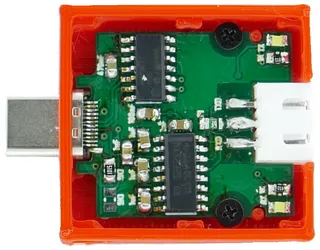
Design was easy enough. To get from USB to TTL UART, I used MCP2221, but any similar chip will work equally well. Resulting TTL signal is then fed into MAX232 where charge pump brings it to RS-232 voltage levels, about ±8 V. This is quite sufficient to be fully RS-232 compliant. Even better, MAX232 will allow for receiving a full RS-232 ±15V signal with some margin. The end result should be that you can interconnect with pretty much any RS-232 compliant device out there.
Unlike for my CAN-bus expansion card, here I went for a slightly bigger connector of JST XH variety. While this one actually required a bit of modification to the expansion card casing, it’s actually much more convenient than its 2.0 mm brethren. First of all, spacing is 2.5 mm which is close enough to 0.1" spacing that you can easily use a standard jumper wires to connect. This means you don’t need any specialized tools or bother with creating a cable yourself. Further more, if you plan to have something more permanent connected and you want the polarity protection you get from JST XH, it’s trivial to find many cables with 3-pin JST XH already present.
Pinout was another difficult choice and in the end I decided onto RXD GND TXD. Benefits of this approach are mostly in the area of safety. If GND wire was at pin 1, there is some place for doubt whether you start counting on left or right. With it being in the middle, that doubt is removed. Further more, to do the self-test, one just needs to connect two outer pins together. Again, it describes connection uniquely without even mentioning pin numbers. Yes, you need pin numbers for RXD and TXD regardless but swapping those two will never cause any damage so the guessing game is less dangerous.
As noted above, the boards were manufactured by PCBWay and there were a few things to watch out for. Due to the connector, these boards had to be 0.8mm. PCBWay does support this thickness without any extra cost and it’s only a click away.
Another thing to watch for, was that this board really does require 6/6 manufacturing process. Interestingly, I accidentally had one via that was too close but my board passed all the checks PCBWay had. When I got it back, I saw that via’s ring was adjusted to be slightly thinner on the offending side so everything ended up working just fine. While I appreciate such help, I would actually prefer the check to fail so I can correct the boards myself instead of silently fixing the issue.
One important thing that had me worried was if small PCB features needed for USB type-C edge connector would be routed correctly. What I discovered by accident was that some board houses do their routing with a 0.068" mill end which is a bit too large for these cutouts. If that happens, you simply cannot fit this connector onto it. What you want is 0.04" mill end to correctly handle this board outline. Either someone was paying attention or PCBWay does this by default. Either way, I got my boards perfectly milled.
If you look at pictures carefully, you will also notice something is off with the silk screen and here I must take a full fault for this. I do love Bahnschrift font and how well it renders at small sizes so I decided to use it for silk-screen markings. But I got greedy and went with its condensed variant that, in retrospective, had no chance of being readable. This one was purely on me.
In any case, boards were in my hands within 10 days. This also meant they arrived faster than I was ready for them but I cannot really hold this against PCBWay. :)
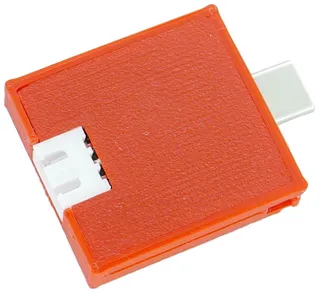
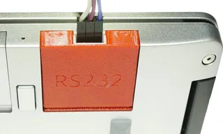
As far as case goes, I toyed with an idea to fit it into the existing USB A case. While this might have been just possible, it also meant for each device one would need to dismantle a perfectly good official expansion card. Thus, I went with 3D printed case with slight modifications. When combined with friction-fit top, card actually doesn’t look half bad.
With everything else out of the way, now comes the part where I tell you about potential issues. The major one is that this is non-insulated interface. RS-322 driver can easily handle ±30 V so this would not be an issue normally. However, for signals to be measured, one needs to have both communicating devices on the same ground potential. And therein lies the major trouble. If you accidentally connect something that is not ground into this, you will pass a significant current and maybe burn down the transceiver. In the worst case you could also damage the laptop as all grounds are connected together.
All that said, as long as you connect ground to ground you should be fine. If you are not sure about the ground potential on the other side, a neat trick is to simply disconnect your laptop from the AC adapter. If you run your laptop of the battery, its ground will “float” and thus you again can rely on ±30 V range of MAX232 chip. This simple trick will give you enough leeway to make many mistakes.
Lastly, there is a slightly unconventional fast (20 ms) fuse on the ground path that might save your butt if things go really bad. Notice that I said “might” and not “will” here. Fuses are great but even a fast fuse will take a decent amount of time to break the connection. Fortunately, type-C ports are quite rugged so odds are decent the motherboard won’t be damaged. But I wouldn’t bet on it.
My personal approach when connecting anything to this expansion card would be to make sure I’m connecting ground on both sides and, as an extra precaution, to test connection with laptop disconnected for the mains. If communication works fine, you can connect laptop back to the mains.
Also note this is nothing specific to this adapter - all non-insulated USB adapters (and most of them are) suffer from the same potential problems. However, due to the size of this expansion card, it’s much easier to misconnect wires then when you’re connecting to the DB-9.
In any case, as always, the design is freely available. If you don’t want to bother soldering one yourself, they are also available for purchase (USA only, at this time).


